
- Explain the operating logic of core ADAS functions mandated under Euro NCAP and UNECE regulations.
- Calculate AEB's Time-to-Collision (TTC) metric and its staged warning→partial-brake→full-brake escalation.
- Analyze ACC's radar/camera fusion requirements and its stop-and-go extension.
- Distinguish the operational difference between LDW and LKA (warning-only vs. active correction) in the SAE L0/L1 context.
- Understand the sensor placement and triggering conditions of BSD, RCTA, and TSR systems.
AD-12 — Core ADAS Features: AEB, ACC, LKA, LCA, BSD, RCTA and TSR
FACT — The planning and control layers covered in AD-10 and AD-11 show up in most production vehicles today as independent, narrow-scope ADAS (Advanced Driver Assistance Systems) features at the L0-L2 level. This lesson treats the seven most common features found in production vehicles — AEB, ACC, LKA/LDW, LCA, BSD, RCTA, and TSR — as a practical catalog, answering, for each one, what it does, which sensors it uses, its core decision logic, and which safety/regulatory driver pushed it into adoption.
- Active Safety and Driver-Assistance Feature Inventory
- AEB (Autonomous Emergency Braking): Time-to-Collision and Staged Intervention
- ACC (Adaptive Cruise Control): Following Distance and Stop-and-Go
- LDW vs. LKA: Warning or Active Correction?
- LCA (Lane Change Assist): Semi-Automated, Driver-Confirmed Lane Changes
- BSD (Blind Spot Detection): Blind-Spot Radar
- RCTA (Rear Cross-Traffic Alert): Cross-Traffic During Reversing
- TSR (Traffic Sign Recognition): Camera-Based Sign Classification
- Comparison Table: Sensor, SAE Level, and Trigger Condition
- Notes from Real Systems
1. Active Safety and Driver-Assistance Feature Inventory
FACT — The core ADAS functions found in a modern passenger vehicle are mandated or incentivized as standard equipment by Euro NCAP’s safety rating and the EU’s General Safety Regulation (GSR II). Each function is a narrow-scope, single-purpose application of the perception/prediction layers from AD-09 and the control layer from AD-11:
| Feature | What It Does | SAE Level |
|---|---|---|
| AEB | Applies automatic braking to avoid/mitigate a collision | L0 |
| ACC | Maintains a set time-gap with the vehicle ahead | L1 |
| LDW/LKA | Warns on lane departure / actively steers back in | L0 (LDW) / L1 (LKA) |
| LCA | Semi-automated lane change with driver confirmation | L2 |
| BSD | Detects vehicles in the lateral/rear blind spot | L0 |
| RCTA | Detects cross-traffic while reversing | L0 |
| TSR | Classifies traffic signs via camera | L0 (informational) |
INTERPRETATION — The SAE levels in this table (per the J3016 classification covered in AD-03) reflect how much of the driving task the feature takes over on its own — L0 features never take the driver off continuous steering/acceleration duty, they only monitor and intervene/warn when needed; L1 features take over continuously along a single axis (either steering or throttle/brake); L2 features take over both, but under driver supervision.
2. AEB (Autonomous Emergency Braking): Time-to-Collision and Staged Intervention
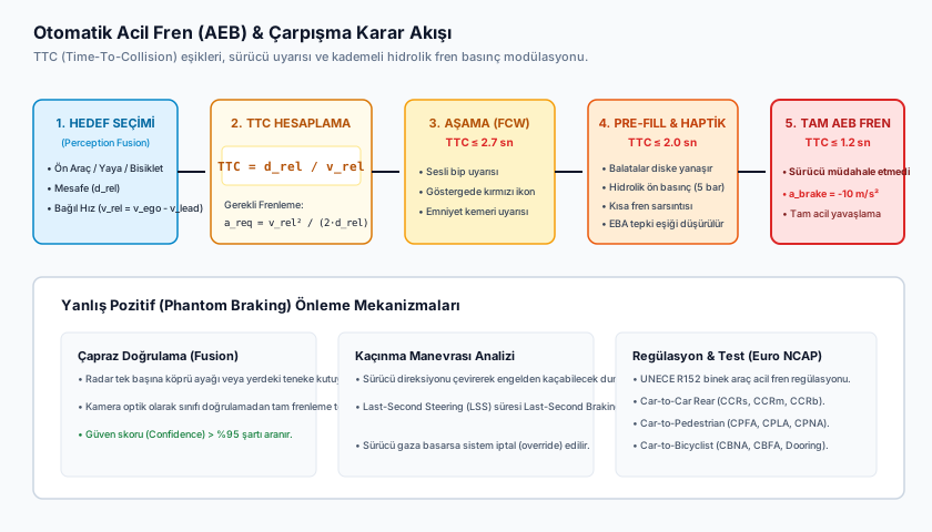
FACT — At the core of AEB’s decision logic is the Time-to-Collision (TTC) metric:
The system continuously tracks distance and relative speed to the object ahead through radar (reliable for distance/speed measurement) and camera (for object classification and in-lane positioning) fusion; as TTC drops below decreasing thresholds, the intervention escalates in stages:
| Stage | Typical TTC Threshold | Intervention |
|---|---|---|
| FCW (Forward Collision Warning) | Audible/visual warning | |
| Brake Prefill | Pads are brought to the disc, cutting response time | |
| Partial Braking | Moderate automatic deceleration (e.g. ) | |
| Full Emergency Braking | Maximum deceleration if the driver hasn’t reacted (e.g. ) |
(The numeric TTC thresholds and deceleration values in this table are illustrative; exact values vary by manufacturer, vehicle mass, and road conditions — [ASSUMPTION: the orders of magnitude here are based on commonly cited public technical descriptions, but each OEM’s calibration differs].)
WARNING — This staged escalation is a deliberate design choice: in the early stages (warning, prefill), the driver is given a chance to regain control; only if the driver fails to react at all does the most severe intervention (full emergency braking) engage. This both prevents false positives (unnecessary hard braking) from eroding driver trust, and preserves the “driver still in control” principle within L0 boundaries.
Regulatory driver: The primary force behind AEB’s spread across production fleets has been Euro NCAP including AEB tests in its overall safety rating, and UNECE R152 combined with GSR II making AEB mandatory on new vehicles in the EU (exact effective dates and scope vary by country/vehicle class, hence marked ASSUMPTION).
3. ACC (Adaptive Cruise Control): Following Distance and Stop-and-Go
ACC builds on classical fixed-speed cruise control: in addition to the driver-set target speed, it tries to maintain an adjustable time-gap (typically ) with the vehicle ahead.
- Sensors: Primary distance/speed measurement comes from a forward-facing radar (long-range, weather-resistant); object classification and lane detection come from a camera; the fusion of the two resolves radar’s “which object is in my lane” ambiguity using the camera.
- Decision logic: If there’s no vehicle ahead or it’s far away, ACC drives to the set target speed; if a vehicle is detected, it continuously adjusts speed to maintain the target time-gap ( is continuously updated based on and distance — this is an application of the longitudinal control loop covered in AD-11 Section 6).
- Stop-and-Go extension: Modern ACC systems extend down to traffic-jam speeds, all the way to a complete stop — if the vehicle ahead stops, ACC stops too; if the vehicle ahead moves again within a few seconds, ACC resumes automatically as well (requiring driver confirmation in some systems).
EXAMPLE — An ACC set to a time-gap on the highway targets roughly of following distance from the vehicle ahead at (); if the vehicle ahead slows down, ACC automatically brakes to maintain this distance, and if it speeds up, ACC accelerates too, up to the set upper speed limit.
4. LDW vs. LKA: Warning or Active Correction?
Lane-tracking functions come in two distinct maturity levels, and this distinction is a concrete example of the SAE L0/L1 boundary covered in AD-03:
- LDW (Lane Departure Warning) — L0: When the camera detects the vehicle approaching or crossing a lane line, it warns the driver audibly/haptically (steering wheel or seat vibration). It sends no command to any actuator — no torque is ever applied to the steering. The driver still retains 100% of the driving task; the system is purely a passive monitor.
- LKA (Lane Keeping Assist) — L1: Uses the same perception chain, but when the lane-departure threshold is approached, it applies an active correction torque through the EPS motor and steers the vehicle back into the lane. From that moment on, the system has effectively taken over part of the driving task along that axis (lateral) — L1 by definition.
CRITICAL — The LDW→LKA transition is the difference between “touching no actuator” and “continuous single-axis actuator control” — this is exactly the criterion SAE J3016’s L0/L1 distinction rests on (AD-03). A system being named “lane keeping” doesn’t determine its automation level; what determines it is whether a command is actually sent to an actuator.
Some manufacturers go beyond these two and offer a proactive Lane Centering Assist function that keeps the vehicle continuously in the middle of the lane — unlike LKA, it runs continuously rather than only at the moment of a lane violation; this is typically bundled as a component of L2 alongside other L2 functions (e.g. ACC).
5. LCA (Lane Change Assist): Semi-Automated, Driver-Confirmed Lane Changes
LCA is a driver-triggered instance of the behavior-planning FSM we saw in AD-10 Section 3: when the driver signals, the system confirms the gap in the target lane (via radar + blind-spot sensors), and if it’s safe, generates the quintic-polynomial lateral trajectory from AD-10 Section 6, which the control layer from AD-11 then executes.
WARNING — LCA is semi-automated: the maneuver is triggered by the driver signaling, and in most systems the driver’s hands cannot fully leave the wheel (monitored via a capacitive steering-wheel sensor). If there isn’t sufficient gap in the target lane, or driver confirmation is withdrawn (turning off the signal, applying counter-torque to the wheel), the maneuver is cancelled immediately.
6. BSD (Blind Spot Detection): Blind-Spot Radar
BSD continuously scans the lateral-rear zones the driver can’t see in the side mirrors using short-to-medium-range corner radars mounted in the vehicle’s rear fenders.
- Sensor: Typically one radar in each rear fender (left and right); some systems supplement this with ultrasonic sensors.
- Decision logic: When a vehicle is detected in the blind-spot zone, a warning indicator lights up in the corresponding side mirror; if the driver signals toward that side, the warning becomes more prominent (flashing, audible alert) — this reflects a common architectural pattern where the same radar hardware is shared with LCA.
- BSD alone is L0 (purely informational, touches no actuator); but it also feeds its data into LCA and, in some combined LKA/LCA configurations, into “evasive steering assist” functions.
7. RCTA (Rear Cross-Traffic Alert): Cross-Traffic During Reversing
RCTA uses the same corner radars as BSD, but with a different scan direction and scenario: while the vehicle is reversing (backing out of a parking spot, exiting a driveway), it detects cross-traffic (another vehicle, a cyclist) approaching not directly from behind but from the vehicle’s sides.
FACT — RCTA’s practical value comes from the physically restricted rear-mirror and rear-window visibility in modern SUVs/pickups and commercial vehicles with tall or enclosed rear bodies — while reversing, a driver may not be able to spot a vehicle approaching from the side with the naked eye or mirrors; RCTA closes this field-of-view gap with radar.
Trigger logic: it activates when the vehicle is in reverse gear; if the detected cross-object’s predicted trajectory intersects the vehicle’s reversing trajectory, an audible/visual warning is issued; some manufacturers add automatic partial braking as well (RCTB — Rear Cross-Traffic Braking).
8. TSR (Traffic Sign Recognition): Camera-Based Sign Classification
TSR is an image-recognition function that classifies traffic signs (especially speed-limit signs, no-overtaking signs) in real time from the forward-facing camera feed.
- Sensor: A single camera (in some systems cross-verified against HD map data — if the map-based speed-limit information is inconsistent with the camera detection, the more reliable source is prioritized).
- Decision logic: The detected speed limit is shown on the instrument cluster; a visual/audible warning may be produced if the driver’s current speed exceeds the limit.
- Integration with ACC: In advanced systems, TSR’s output is fed directly into ACC — a “speed-limit-aware ACC” automatically suggests, or (with driver confirmation) sets, a new target speed based on the newly detected limit.
ASSUMPTION — TSR’s accuracy is sensitive to weather conditions, sign dirt/damage, and regional sign-standard differences; that’s why most manufacturers position TSR output as “informational/advisory” rather than “binding” — exact accuracy rates and rollout strategies vary by manufacturer.
9. Comparison Table: Sensor, SAE Level, and Trigger Condition
| Feature | Primary Sensor(s) | SAE Level | Typical Trigger Condition |
|---|---|---|---|
| AEB | Forward radar + camera | L0 | dropping below decreasing thresholds |
| ACC | Forward radar + camera | L1 | Distance/time-gap to lead vehicle deviating from target |
| LDW | Forward camera | L0 | Approaching/crossing a lane line (warning) |
| LKA | Forward camera | L1 | Approaching/crossing a lane line (active torque) |
| LCA | Forward camera + corner radar | L2 | Driver signal + confirmed gap in target lane |
| BSD | Rear corner radar | L0 | Vehicle detected in the blind-spot zone |
| RCTA | Rear corner radar | L0 | In reverse gear, cross-trajectory intersection detected |
| TSR | Forward camera | L0 | Traffic sign detection/classification |
10. Notes from Real Systems
ASSUMPTION — The notes below rely on publicly available technical publications and regulatory texts; manufacturer-specific calibration/exact threshold values are not fully public.
- Mobileye’s EyeQ system-on-chip family is a widely cited architectural example, supplied to numerous OEMs, of a single camera perception output feeding multiple functions simultaneously — AEB, LDW/LKA, and TSR — showing that different ADAS functions are generally built on a shared perception backbone (perception output is shared, decision/control logic is separated by function).
- Euro NCAP’s test protocols (AEB Urban/Interurban/Pedestrian/Cyclist scenarios, Lane Support Systems — LSS tests) are publicly available reference documents that define what performance these functions must demonstrate in which scenarios, and that directly shape manufacturer design decisions.
- Hardware sharing between RCTA and BSD (the same corner radars) is a common engineering pattern to lower production cost, but the two functions’ decision logic and triggering scenario (parking/reversing vs. normal driving) are independent of each other.
Frequently Asked Questions (FAQ)
Q: Why does AEB sometimes brake on a “false positive”?
This usually stems from a temporary ambiguity in radar/camera fusion (e.g. a roadside object briefly misclassified as being in-lane) or a temporary intersection between the ego vehicle’s lane and a laterally approaching vehicle’s trajectory; manufacturers continuously calibrate fusion thresholds and TTC calculation windows to reduce this rate.
Q: Do ACC and LCA run at the same time?
Yes, in many production L2 packages the two are offered together: ACC handles longitudinal control (following distance) while LCA/Lane Centering handles lateral control — this combination is often marketed under package names like “Highway Driving Assist” and will be covered in detail in AD-13.
Q: Why does TSR sometimes show the wrong speed limit?
Common causes include temporary/construction signage, transition zones between different country/regional sign standards, and physically dirty or damaged signs; that’s why TSR is usually cross-verified against map data and presented as informational.
Summary
- Core ADAS functions are narrow-scope, single-purpose production applications of the planning/control layers covered in AD-10/AD-11.
- AEB works via TTC-based staged escalation — warning → prefill → partial brake → full brake; its regulatory drivers are Euro NCAP and UNECE R152.
- ACC automates longitudinal following via time-gap logic, extending to stop-and-go in modern systems.
- The LDW (warning-only, L0) vs. LKA (active torque, L1) distinction is a concrete example of the SAE automation level resting on whether a command is actually sent to an actuator.
- LCA performs driver-confirmed, semi-automated lane changes; BSD and RCTA share the same corner-radar hardware but operate in different scenarios (lateral cruising vs. reversing); TSR enables speed-limit-aware ACC via camera-based sign classification.
Sources and Verification Note
This lesson is based on Euro NCAP’s AEB and Lane Support Systems (LSS) test protocols, the texts of UNECE R152 (AEB regulation) and UNECE R79 (steering equipment), and SAE J3016’s automation-level definitions (see AD-03). Notes on the Mobileye EyeQ architecture and manufacturer-specific TTC/deceleration thresholds are based on publicly available technical sources and are marked ASSUMPTION above. The lastVerified date is the date of this lesson’s last technical review.
Next Lesson
- AD-13 — Highway Assist and Highway Pilot Systems: We’ll examine how the ACC and LCA/Lane Centering functions covered separately in this lesson combine into an integrated, driver-supervised L2 “Highway Pilot” system, along with handover logic and driver-monitoring systems.
Technical Diagrams
Quiz
What is the AEB stage where calipers kiss the rotors under low pressure prior to full braking?
Brake Prefill primes the hydraulic circuit to eliminate response latency.
What is the key functional difference between LKA and LCA?
LKA reacts at boundaries; LCA continuously centers.
Why is ACC following distance parameterized in seconds (Time Gap)?
Constant time gap ensures physical clearance scales quadratically with speed.
Which sensors enable Rear Cross Traffic Alert (RCTA)?
Rear corner radar sensors scan cross-approaching traffic up to 30m.
How does AEB behave if the driver firmly depresses the accelerator pedal during an event?
Positive driver throttle override takes priority over automated braking.
Glossary
| English Term | Definition |
|---|---|
| Advanced Driver Assistance Systems (ADAS) | Electronic and algorithmic active safety systems designed to enhance driver situational awareness, issue warnings, or intervene via steering/braking to mitigate collisions. |
| Time-to-Collision (TTC) | The remaining time in seconds before two vehicles collide if their relative speed and heading remain unchanged (TTC = relative_distance / relative_velocity). |
| Autonomous Emergency Braking (AEB) | An active safety system that monitors the forward path using radar/camera fusion and automatically commands emergency deceleration when an imminent collision is detected and the driver fails to react. |
| Global Vehicle Target (GVT) | A radar/LiDAR-reflective, inflatable/soft, realistic vehicle target used in physical test/validation stages (including Euro NCAP protocols) for systems like AEB, allowing safe collision-risk testing without damaging a real vehicle if actually struck. |