
- Explain why, in the absence of a human DDT-fallback, Level 4 robotaxi architecture requires categorically different engineering than a Level 2 consumer vehicle.
- Analyze why redundant sensor coverage based on overlapping fields of view (FOV) prevents a single sensor failure from creating a blind spot.
- Evaluate the primary/secondary compute architecture and the role of the backup controller that executes a Minimal Risk Maneuver (MRM).
- Understand the place of redundant steering/braking actuation and independent power distribution networks in fail-operational design.
- Explain the Minimal Risk Condition (MRC) concept with a concrete robotaxi-context example.
- Distinguish remote assistance (teleoperation) from real-time remote driving, and understand why fleet operations (dispatch, cleaning, charging, maintenance) constitute a separate engineering problem.
AD-15 — Robotaxi Architecture: Hardware Redundancy and Fleet Operations
FACT — In a Level 2 consumer vehicle, if the steering motor fails, the driver can still hold the mechanical steering linkage and pull the vehicle over safely — the human remains the ultimate fallback. But in a Level 4 robotaxi, by definition (see AD-02), there is NO driver in the cabin to take on that role. This single difference sets robotaxi engineering apart from consumer ADAS engineering categorically: every safety-critical subsystem must have a hardware/software redundancy that substitutes for the missing human fallback.
In this lesson we examine the robotaxi architecture’s “No Single Point of Failure” principle, its concrete manifestations across the sensing, compute, actuation, and power layers, the Minimal Risk Condition (MRC) concept, and the fleet-operations concerns that go beyond single-vehicle engineering:
- Why Is L4 Categorically Different: The Absence of a Human Fallback
- Redundant Sensor Coverage: Overlapping Fields of View (FOV)
- Redundant Compute: Primary/Secondary Compute and the MRM Controller
- Redundant Actuation and Power: Steering, Braking, Electrical Redundancy
- Minimal Risk Condition (MRC): A Concrete Robotaxi-Context Example
- Fleet Operations I: Remote Assistance (Teleoperation) — Not Real-Time Driving
- Fleet Operations II: Monitoring, Dispatch, Cleaning/Charging/Maintenance Logistics
- Real-World Example: Waymo’s Approach
1. Why Is L4 Categorically Different: The Absence of a Human Fallback
Under the SAE J3016 taxonomy, the defining feature of Level 4 is that the system also takes on DDT-fallback (intervention at a moment of uncertainty/failure) within the defined ODD — unlike Level 3, the human does not need to be “ready to take over at any moment,” because in most robotaxi configurations there isn’t even a driver’s seat to take over from.
CRITICAL — Engineering-wise, this means: when a Level 2 vehicle’s steering motor, brake pump, or primary processor fails, the system can say “hand control back to the driver” and the problem is resolved. If a robotaxi fails, there is no one to hand off to — the system ITSELF must either keep operating safely after the failure (fail-operational) or at minimum be able to bring itself to a safe stop on its own (fail-safe). This distinction gives rise to the “No Single Point of Failure” principle: the failure of any single sensor, wire, power line, compute unit, or actuator must not eliminate the vehicle’s ability to reach a safe stop.
This principle is applied separately across four layers: sensing, compute, actuation, power. The next three sections examine each layer in turn.
2. Redundant Sensor Coverage: Overlapping Fields of View (FOV)
The camera/radar/LiDAR trio covered in AD-04 is present in every AD system, including a robotaxi — but in robotaxi architecture, the placement of these sensors follows a single governing principle: no single sensor’s failure should create a blind spot.
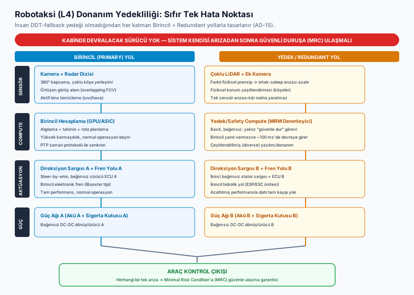
- Multi-Modal Overlap: Every direction around the vehicle (front, rear, side, corners) is scanned simultaneously by at least two different sensor modalities (e.g., camera + radar, or camera + LiDAR). If a camera lens gets covered in mud, or a radar experiences interference, that region’s coverage isn’t lost entirely — the other modality remains active.
- Physical Position Diversity: Multiple sensors of the same modality (e.g., 2-4 LiDAR units) are placed at different corners of the vehicle; if one is physically damaged (rock chip, collision), the others still partially cover that region.
- Active Cleaning Systems: High-pressure fluid jets and compressed air nozzles instantly clear bugs, mud, and rain buildup from lens/sensor surfaces — this is the “failure prevention” layer (preserving coverage before it degrades, rather than waiting for a failure).
FACT — Redundant sensor coverage is NOT simply mounting two of the same sensor (naive duplication). The real engineering challenge is overlapping the fields of view of sensors that operate on fundamentally different physical principles (camera = passive visible light, radar = active electromagnetic wave, LiDAR = active laser) such that one modality’s systematic weakness (dense fog for cameras, thin metal objects for radar, highly reflective surfaces for LiDAR) is compensated for by another.
3. Redundant Compute: Primary/Secondary Compute and the MRM Controller
The robotaxi’s “brain” doesn’t live in a single compute unit. The typical architecture is two-layered:
- Primary Compute: A high-performance processing cluster, usually accelerated by GPU/ASIC hardware, that executes perception (sensor fusion, object detection), prediction (the intent of other vehicles/pedestrians), and route planning entirely in real time. This is the system’s “normal operation” brain — complex, computationally expensive, but potentially fragile against a single hardware failure.
- Secondary/Backup Compute (Safety Compute): A controller that runs independently of the primary system, generally far simpler and far less computationally demanding. Its job isn’t complex route planning — it asks a single question: “is the primary system behaving as expected, and if not, how do I bring the vehicle to a safe stop?” If the primary system stops responding (freeze, crash, inconsistent commands), the backup controller takes over and executes a predefined, conservative Minimal Risk Maneuver (MRM) to guide the vehicle to a safe stop (see Section 5).
INTERPRETATION — The distinction between these two layers is deliberate: the backup controller doesn’t try to match the primary system’s performance — it focuses on executing a far narrower task (stop safely) with far higher reliability. This is the MRM concept we encountered in the ALKS context in AD-13, now executed by a second computer instead of a human driver — since a robotaxi has no “human to take over,” this second computer is the architectural element that stands in for the human.
Primary and backup compute units are typically linked via a timing protocol (e.g., PTP — Precision Time Protocol) for synchronization, so the backup unit can detect, with no added delay, exactly when it needs to take over.
4. Redundant Actuation and Power: Steering, Braking, Electrical Redundancy
No matter how redundant the compute layer is, the final link where commands reach the physical world — steering, braking, power — must follow the same principle.
- Redundant Steering Actuation: In modern steer-by-wire architectures, the steering motor may run on a single shaft but have two independent stator windings and two separate driver ECUs. If one winding or driver circuit fails, the other continues steering the vehicle (perhaps at reduced performance, but without total loss).
- Redundant Brake Actuation: In addition to the primary electronic brake system (e.g., an iBooster-type unit), there is an independent secondary brake path (e.g., the ESP/ESC unit’s own hydraulic control capability). If the primary brake loses power, the secondary path can still slow and stop the vehicle.
- Redundant Power Distribution: The vehicle’s electrical architecture is split into two independent power networks (e.g., separate batteries, separate fuse boxes, and in some designs even separate DC-DC converters). Even if one power line experiences a short circuit or battery failure, the other line keeps powering critical compute units and actuators.
CRITICAL — This trio (steering, braking, power) is where fail-operational design becomes concrete: for each, the question isn’t “what happens if it fails?” but “when it fails, CAN the vehicle still reach a safe stop?” Redundancy doesn’t exist to prevent failure — it exists to guarantee the ability to reach a Minimal Risk Condition even after a failure occurs.
5. Minimal Risk Condition (MRC): A Concrete Robotaxi-Context Example
AD-17 covers this concept in full; here we introduce it with a concrete example in the robotaxi context.
Minimal Risk Condition (MRC) is the stopped state a vehicle can reach when it or its surroundings experience a failure/uncertainty, one in which risk has been reasonably reduced (e.g., pulling to the shoulder with hazard lights on and stopping). Minimal Risk Maneuver (MRM) is the maneuver itself (the brake + steering + signaling sequence) executed to reach that state.
EXAMPLE — A robotaxi’s primary compute unit stops responding in heavy traffic due to a software exception. The backup controller (Section 3) detects this within 100 milliseconds and takes over:
- It gradually slows the vehicle within its current lane (not a sudden stop — a gradual one, to reduce rear-collision risk).
- It activates the hazard lights and, if possible, moves to the nearest safe lane (shoulder, right lane).
- It brings the vehicle to a complete stop, keeps the doors locked (for passenger safety), and automatically sends a failure notification to the fleet operations center (see Sections 6-7).
- The vehicle remains in this safe, low-risk state until a remote operator or an on-site technician intervenes.
FACT — MRC does not always mean “pull over to the side of the road” — it varies with context. On a highway with a shoulder, pulling over there may be the MRC; at an urban intersection, “clear the intersection and stop at a safe point beyond it” may be more appropriate. What matters is that MRC is a predefined, ODD-specific target state that can be reached quickly, without entering a complex decision-making process at the moment of failure.
6. Fleet Operations I: Remote Assistance (Teleoperation) — Not Real-Time Driving
Beyond single-vehicle engineering (Sections 2-5), operating a robotaxi requires a separate engineering discipline: fleet operations. The most commonly misunderstood piece of this is remote assistance (teleoperation).
WARNING — Teleoperation is NOT the vehicle being driven remotely in real time via joystick, like a video game. Even tenths-of-a-second delays (latency + jitter) over a cellular network make real-time remote control of a vehicle moving at speed unacceptable from a safety standpoint — the vehicle could be left uncontrolled the instant the signal drops.
Real-world deployments instead use a tele-guidance model:
- The vehicle encounters an uncertain situation its local perception/planning stack can’t resolve on its own (e.g., a garbage truck partially blocking the road, a police officer directing traffic by hand, a lane closure not present on the map).
- The vehicle first stops on its own decision — this is the default safe behavior at a moment of uncertainty.
- Camera footage and the alternative trajectory options the vehicle proposes are sent to a human operator at the fleet operations center.
- The operator does not drive the vehicle — they only provide a high-level approval/denial: “you may pass the obstacle on the left” or “I approve this lane change.”
- While its own local perception and collision-avoidance systems remain in full authority, the vehicle executes only the approved plan through its own controller — the operator never sends a direct steering/throttle/brake command.
CRITICAL — This distinction is critical: the operator’s role is to resolve semantic ambiguity (is this a garbage truck or an abandoned vehicle, does this maneuver comply with traffic rules), while the vehicle’s role is to always retain real-time safety execution on its own. Even with latency, low bandwidth, or a lost connection, the vehicle can remain safe because collision avoidance runs locally, independent of network connectivity.
7. Fleet Operations II: Monitoring, Dispatch, Cleaning/Charging/Maintenance Logistics
Beyond teleoperation, operating a robotaxi fleet creates genuine operational-engineering problems never encountered in single-vehicle engineering:
- Fleet-Wide Monitoring: A network operations center (NOC-like structure) tracks the location, health status (sensor/battery/compute-unit diagnostic data), active trips, and MRC status of hundreds/thousands of vehicles in real time. This is necessary to distinguish a single vehicle’s “failure” from a systemic issue that could affect the entire fleet (e.g., a bug surfacing in a specific software release).
- Dispatch: Deciding which vehicle gets assigned to which ride request isn’t just finding the nearest vehicle — it’s a problem that simultaneously optimizes constraints like battery/fuel sufficiency, how soon the vehicle is due for its next scheduled maintenance/cleaning, and ODD boundaries (e.g., some vehicles may not yet be certified for certain neighborhoods).
- Cleaning Logistics: In a vehicle with no human driver, whose responsibility is cabin cleanliness (trash left by a passenger, spills, mess)? Fleet operators handle this either by building a dedicated “cleaning crew + depot” network, or by using interior cameras/sensors that detect contamination and automatically pull the affected vehicle out of service.
- Charging Logistics: For an electric robotaxi fleet, when and where vehicles charge must be planned so it doesn’t reduce fleet capacity during high-demand hours (rush hour) — this sits at the intersection of a passenger-transportation optimization problem and an energy-management problem.
- Maintenance Logistics: Periodic calibration of sensors (especially LiDAR and cameras), replacement of wearing parts (brake pads, tires), and staged/safe rollout of software updates across the fleet (an update goes first to a small subset for validation, not the entire fleet at once) constitute a continuous operational burden.
INTERPRETATION — None of these problems are “autonomous-driving algorithms” — they’re all classic fleet/logistics management problems. But because a robotaxi fleet has no human driver, tasks a traditional taxi/ride-hailing fleet’s driver handles spontaneously (cleaning the car, refueling/charging, noticing and reporting an issue) must now be explicitly designed by a centralized engineering system. This explains why running a robotaxi operation requires being not just an “autonomous driving company” but also a “fleet logistics company.”
8. Real-World Example: Waymo’s Approach
Waymo is the longest-running and most extensively publicly documented Level 4 robotaxi operation in the world — a commercial passenger service on public roads with no safety driver in the cabin. Its published safety reports and technical documentation illustrate the real-world counterpart of the principles covered in this lesson:
- Redundant sensor suite: Multiple LiDAR units (long-range plus perimeter short-range), a high-resolution camera array, and radar in the rooftop sensor pod, with overlapping fields of view providing uninterrupted 360° coverage.
- Redundant compute and actuation: An independent backup system, alongside the primary driving computer, capable of guiding the vehicle to MRC upon a failure; redundant actuation paths for steering and braking.
- Remote assistance model: Waymo’s public statements emphasize that remote operators do NOT drive the vehicle in real time — they provide high-level guidance/approval at moments of uncertainty when the vehicle has already stopped on its own decision (consistent with the tele-guidance model in Section 6).
- Fleet operations center: An operational structure that centrally manages vehicle health, trips, and the maintenance/cleaning/charging cycle.
ASSUMPTION — Cruise (a GM subsidiary) was another publicly documented example of a Level 4 operation, having historically run a public robotaxi service in cities such as San Francisco. However, because the operational status of robotaxi companies (active fleet size, cities served, or even whether a service has been discontinued entirely) can change rapidly over time, this lesson does not present Cruise’s or any other operator’s current operational status as settled fact — readers should separately verify current status through official sources (company announcements, regulatory filings).
Frequently Asked Questions
Q1: Is redundant compute just running the same software twice? No. The common approach is diverse redundancy: the primary system runs the complex perception/planning stack, while the backup system is a much simpler, independently written “safe stop” controller. The goal isn’t to verify the same computation twice — it’s to provide an independent path that can bring the vehicle to a safe stop even if the primary system becomes completely unresponsive.
Q2: Can a robotaxi fleet be operated without teleoperation? Theoretically yes — the vehicle could pull itself into MRC at every moment of uncertainty on its own. But in practice, this leads to unnecessarily frequent “stop and wait” events over situations that are actually resolvable (e.g., a police officer directing traffic); tele-guidance resolves most of these within minutes, improving service continuity.
Q3: Is a robotaxi’s MRC always “pull over to the side of the road”? No — MRC varies with the ODD and the type of failure (see Section 5). A failure in the middle of an intersection may require “clear the intersection and stop at a safe point”; on a highway with a shoulder, pulling over there may be more appropriate. MRC is always a predefined target state — it isn’t chosen arbitrarily at the moment of failure.
Summary
- Because Level 4 robotaxis have no human DDT-fallback, every safety-critical subsystem must be designed under the “No Single Point of Failure” principle.
- Redundant sensor coverage overlaps the fields of view of sensors built on different physical principles (camera, radar, LiDAR) so that one modality’s weakness is compensated for by the others.
- Redundant compute consists of a complex primary system and a far simpler, independent backup “safe stop” controller; the backup doesn’t match the primary’s performance — it only guarantees a safe stop.
- Redundant steering/braking/power is where fail-operational design becomes concrete, guaranteeing that the vehicle can reach a Minimal Risk Condition even after a failure occurs.
- MRC is a predefined stopped state reached at a moment of failure/uncertainty that reasonably reduces risk; MRM is the maneuver executed to reach it (covered fully in AD-17).
- Teleoperation is not real-time remote driving — remote operators provide high-level semantic approval/guidance, while the vehicle’s own local safety systems always retain full authority.
- Fleet operations (monitoring, dispatch, cleaning, charging, maintenance) constitute a genuine, separate operational-engineering discipline beyond single-vehicle engineering.
- Waymo is the principal publicly documented real-world example of these principles.
Sources and Verification Note
- ISO 26262 (Functional Safety — Road Vehicles)
- ISO 21448 (SOTIF — Safety of the Intended Functionality)
- SAE J3016:2021 (Taxonomy and Definitions for Terms Related to Driving Automation Systems)
- UL 4600 (Standard for Evaluation of Autonomous Products)
- Waymo Safety Reports (publicly available safety and architecture documentation)
- UNECE Regulation No. 157 (ALKS — for conceptual comparison of MRM/TOR)
ASSUMPTION — Because the current fleet size, cities served, and exact hardware-architecture details of robotaxi operators (Waymo, Cruise, Baidu Apollo, and others) are updated frequently and are partly proprietary, this lesson relies on architectural principles rather than exact/current figures; readers should consult the relevant companies’ official safety reports and regulatory filings for current status.
Next Lesson
- AD-16 — Operational Design Domain (ODD): Definition, Taxonomy and Boundaries: The formal taxonomy of the ODD concept we’ve referenced throughout these lessons, methods for defining its boundaries, and how a system’s ODD is validated.
Technical Diagrams
Quiz
Why is the 'No Single Point of Failure' design mandate non-negotiable for Level 4 Robotaxis?
Without an in-cabin human fallback, any primary failure must be mitigated by redundant hardware.
What is the function of the fluid and compressed air nozzles mounted on robotaxi sensor pods?
Active cleaning nozzles clear lens contamination in real time to prevent sensor blindness.
How is fail-operational redundancy achieved in a modern robotaxi steering actuator?
Dual-wound electric steering motors maintain control authority even if one electrical channel fails.
What constitutes safe operational procedure during robotaxi fleet teleoperation?
Cellular latency precludes direct remote driving; tele-guidance provides semantic path authorization.
What is the primary scope of the UL 4600 autonomous mobility standard?
UL 4600 provides the principles and evidence-based structure for autonomous safety cases.
Glossary
| English Term | Definition |
|---|---|
| Automated Driving System (ADS) | The hardware and software collectively capable of performing the entire Dynamic Driving Task (DDT) on a sustained basis within an ODD (SAE Levels 3, 4, and 5). |
| Minimal Risk Maneuver (MRM) | The specific maneuver executed, upon detecting an ODD violation or system malfunction, to bring the vehicle to a Minimal Risk Condition (MRC) — e.g. gradually decelerating to a stop while maintaining lane. Unlike MRC (the resulting state), MRM refers to the process/action. |