
- Precisely explain SAE J3016's definition of DDT Fallback and how that responsibility is distributed between system and human across L1 through L5.
- Analyze how the Minimal Risk Manoeuvre (MRM) differs between L2/L3 (escalating alerts plus controlled in-lane deceleration) and L4 (fully autonomous execution).
- Quantitatively evaluate, via rear-end collision kinematics, why gradual in-lane deceleration is preferred over an abrupt hard stop.
- Draw a clean conceptual distinction between MRM (the process) and MRC (the resulting state).
- Understand how escalating-alert HMI design balances false-alarm annoyance against genuine urgency, and why this is inseparable from driver monitoring (AD-18).
AD-17 — Fallback Strategies, MRM and Minimal Risk Condition (MRC)
FACT — In AD-16 we established what should happen once a system approaches or exits its ODD boundary, but not how. SAE J3016 defines that “how” precisely under the term DDT Fallback: the response by the user (driver) or by the ADS to either continue performing the DDT (Dynamic Driving Task) or achieve a Minimal Risk Condition (MRC), following a DDT performance-relevant system failure or an ODD exit. This lesson examines the last line of defense in automated driving — the engineered mechanism that prevents a boundary exit or a fault from turning into a collision.
In this lesson, you will learn:
- The SAE J3016 Definition of DDT Fallback and Its Distribution of Responsibility by Level
- MRM (Minimal Risk Manoeuvre): Defined as a Process, and the L2/L3 Architecture
- Why Gradual In-Lane Deceleration, Not an Abrupt Stop: the Kinematics of Rear-End Risk
- Fully Autonomous MRM at L4: From a Generic Emergency to “Find a Safe Pull-Over Spot”
- MRC (Minimal Risk Condition): Defined as a State, and Its Distinction from MRM
- Escalating-Alert HMI Design: False-Alarm Annoyance vs. Genuine Urgency
- The Bridge to AD-18: Why Correct Escalation Timing Requires Driver Monitoring
- A Worked End-to-End Timeline
1. The Definition of DDT Fallback and Its Distribution of Responsibility
FACT — SAE J3016’s DDT Fallback definition covers two triggers at once: (a) a performance-relevant system fault (hardware/software failure) and (b) an ODD exit (AD-16). In both cases the objective is identical: produce a response that either lets the vehicle continue performing the DDT, or brings it to a Minimal Risk Condition (MRC).
This responsibility is distributed fundamentally differently across SAE levels:
| Level | Fallback Owner | Mechanism |
|---|---|---|
| L1 / L2 | 100% human driver | The system may disengage silently (or with a brief alert) at any moment; because the driver remains continuously “in-the-loop” (AD-02), control transfer is seamless. |
| L3 | Shared — human first, then the system | The system issues a Take-Over Request (TOR); if the driver does not respond within a defined window (typically a few seconds up to roughly 10 seconds), the system automatically executes its own MRM. |
| L4 | 100% system (ADS) | There is no driver assumed to perform fallback in the cabin — upon any fault/ODD-exit, the system executes MRM entirely on its own, with no TOR or wait window. |
| L5 | 100% system (ADS) | No ODD restriction (all conditions), fallback always resides with the system. |
CRITICAL — L3 is the most fragile row in this table: the system temporarily permits the driver to be “not the DDT’s observer” (off-the-loop, AD-02), yet at the moment fallback is triggered, it requires that same driver to regain full control within seconds. How reliably this transition window is managed depends directly on the quality of the driver monitoring systems that are the subject of AD-18.
2. MRM (Minimal Risk Manoeuvre): Defined as a Process
The Minimal Risk Manoeuvre (MRM) is the dynamic, tactical driving action executed after fallback is triggered, in order to bring the vehicle to a Minimal Risk Condition (MRC, §5) — that is, MRM is a process, not a state.
2.1 Typical L2/L3 MRM Architecture
At L2/L3, where the driver remains a potential fallback source, MRM follows a two-stage structure:
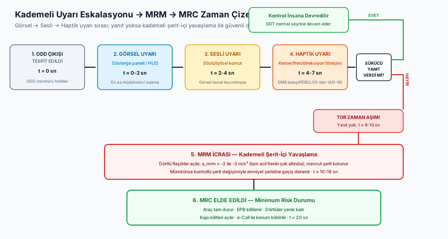
Stage A — Escalating Alert: The system first calls on the driver to take over; this call intensifies over time (detailed in §6): visual alert → audible alert → haptic alert (seatbelt pretensioner pulse, brake pedal jolt, steering wheel vibration).
Stage B — Automated Deceleration (if unanswered): If the driver does not respond within the defined window, the system begins decelerating gradually, while holding its current lane. This is not a “stop” command; it is a “controlled approach toward a safe point” command.
2.2 Why Gradual, Not Abrupt, In-Lane Deceleration?
CRITICAL — This is MRM’s single most critical design decision: within live traffic flow, an abrupt, hard full stop creates a brand-new collision risk of its own. Let’s quantify this.
Unlike scenarios where the vehicle must brake urgently against a threat directly ahead (Automatic Emergency Braking, covered in AD-06/AD-11), at the moment MRM triggers there is no immediate hazard ahead — the trigger is the driver’s non-response or an internal system fault. In that situation, other drivers following behind cannot anticipate an unexpected full-power braking event:
Here is the shared speed of both vehicles, is the following driver’s perception-reaction time (typically 1–1.5 s, longer for a genuinely surprising event), and is the following vehicle’s braking deceleration. If the lead vehicle (executing MRM) brakes at , the gap-closure differential between the two vehicles determines collision risk:
As (the lead vehicle’s braking severity) increases, grows as well — meaning the harder the lead vehicle brakes, the larger the gap the surprised following driver must close. This is exactly why MRM design deliberately keeps within a comfort/safety-balanced deceleration band ( to , far below the to band of a true emergency stop) — predictable enough for trailing traffic to react to, yet effective enough to bring the vehicle to a safe stop within a reasonable time.
Holding the current lane is part of the same logic: an abrupt lane change may be perceived by a vehicle in the adjacent blind spot as an unexpected maneuver, creating a fresh collision risk of its own — which is why the first response is always hold lane + decelerate gradually, with a controlled lane change to the shoulder attempted as a second step only if conditions (an available shoulder, permitting traffic) allow it.
EXAMPLE — Take (), , . Comparing (gradual MRM) against a hypothetical (“abrupt full-stop MRM”): with the former, negative (the gap between vehicles closes slowly; the following driver comfortably keeps pace); with the latter, of extra gap-closure is added on top of the following driver’s baseline reaction distance. The exact numbers vary by scenario, but the direction is unambiguous: as braking deceleration increases, rear-end collision risk grows sharply.
3. Fully Autonomous MRM Execution at L4
At L4 (and L5), a reliable human fallback source in the cabin cannot be assumed — so the system executes MRM entirely on its own upon any trigger, without a TOR or wait window. But “MRM” is not a single fixed action; it is a family of behaviors that differs by the urgency of the fault/condition:
| Fault/Condition Class | Typical L4 MRM Response | Rationale |
|---|---|---|
| Generic emergency (critical sensor loss, sudden obstacle) | Controlled, gradual in-lane stop | No decision time available; the fastest safe option is an in-lane stop |
| Less urgent fault (e.g., degradation of a single redundant sub-system, a planned ODD conclusion) | “Find a safe pull-over spot” — shoulder, parking lot entrance, designated bay | Low time pressure; an MRC that doesn’t block traffic and lets occupants exit safely is preferred |
| Risk of power/energy depletion (e.g., critically low battery) | Early, planned search for an MRC | The vehicle must reach an MRC before it loses the power needed to complete MRM at all |
INTERPRETATION — This differentiation shows why L4 systems need a far more sophisticated decision tree than a simple “stop on any fault” rule: for a robotaxi fleet, vehicles that repeatedly come to rest mid-lane (blocking traffic) create a safety and operational risk in their own right — so a “find and pull over” strategy is preferred whenever possible, with an immediate in-lane stop reserved for genuinely high-urgency cases.
4. MRC (Minimal Risk Condition): Defined as a State
FACT — The Minimal Risk Condition (MRC) is the stable, stationary, safe final physical state the vehicle reaches at the end of the MRM (process). If MRM is the action itself, MRC is where that action arrives.
This distinction may seem conceptually minor, but it is vital from an engineering/regulatory standpoint: when a safety requirement is written as “the system shall reach MRC within X seconds,” that phrasing requires separately validating both the duration of the MRM (the process) and the acceptance criteria of the MRC (the arrived-at state) — is the vehicle fully stopped, is the parking brake engaged, are hazard lights on, can occupants safely exit. A typical MRC includes:
- The vehicle fully stopped (zero speed, persistently).
- Electronic parking brake (EPB) engaged — the vehicle does not rely solely on the foot brake.
- Hazard lights active.
- Where possible, door locks unlocked and an emergency notification (e.g., eCall) sent.
- A location chosen to minimize traffic-blocking risk (a shoulder/safety lane preferred over stopping mid-lane where avoidable).
5. Escalating-Alert HMI Design
How the takeover request is communicated to the driver is a direct engineering problem within MRM’s first stage (§2.1, Stage A), and it carries a classic trade-off:
WARNING — If alerts trigger too early or too often (over-sensitive thresholds), drivers learn over time to ignore them (alarm fatigue / the “cry wolf” effect) — which lengthens reaction time during a genuine emergency. If alerts trigger too late or too rarely, the driver is left with insufficient time to take over. The correct threshold is a data-driven balance point between the two, not an arbitrary fixed number.
Production systems resolve this trade-off through a multi-stage structure that escalates modality over time:
| Stage | Modality | Typical Timing | Physiological Rationale |
|---|---|---|---|
| 1 | Visual (instrument cluster/HUD icon, color change) | t = 0 s | Least intrusive; immediately noticed if attention is already near the road/display axis |
| 2 | Audible (alert tone/spoken prompt) | t ≈ 2–4 s | The visual channel may have been missed (eyes closed/looking away); the audible channel is direction-independent |
| 3 | Haptic (seatbelt pretensioner pulse, brake pedal vibration, steering wheel vibration) | t ≈ 4–7 s | If both visual and audible channels were missed (e.g., driver asleep), tactile stimulus is physiologically the hardest channel to ignore |
| 4 | MRM Onset (automated gradual deceleration) | t ≈ 8–10 s (if unanswered) | The entire HMI escalation has been exhausted; the vehicle itself must now act |
INTERPRETATION — This four-stage structure is not arbitrary — each stage is built on the assumption that the previous one has failed, and each subsequent stage targets a scenario of progressively diminished human attention. The ordering (visual → audible → haptic) is deliberate: it proceeds from least intrusive to hardest-to-ignore, so a mildly distracted driver can respond and “quiet” the system as early as stage one, while only genuinely severe cases (sleep, loss of consciousness) drive the escalation all the way to the end.
6. The Bridge to AD-18: Why Correct Timing Requires Driver Monitoring
The table above conceals an assumption: how does the system actually know whether the driver has genuinely responded at each stage? A naive system can only check for direct action evidence (touching the wheel, pressing a pedal) — but that does not guarantee the driver is cognitively ready to take over (their eyes may still be on a phone even if their hands are reflexively on the wheel).
CRITICAL — This is the exact conceptual bridge connecting AD-17 to AD-18: getting the escalation timing correct — that is, knowing precisely when to move to the next, more intrusive stage — requires the system to know the driver’s actual attention/wakefulness state. A blind timer that simply says “10 seconds elapsed, auto-advance to the next stage” risks both unnecessary early escalation (when the driver is in fact attentive) and dangerously late escalation (waiting through a fixed window when the driver is in fact asleep). Driver Monitoring Systems (DMS, the subject of AD-18), using signals such as eye-closure duration and gaze direction, make it possible to dynamically tune this timing to the driver’s actual state.
7. A Worked End-to-End Timeline (L3 System)
ASSUMPTION — The second-level figures in the timeline below (stage durations, the TOR timeout window, the MRM deceleration rate) are illustrative and conceptual; in real production systems these values vary by regulatory framework (e.g., UNECE R157), the manufacturer’s own safety-engineering decisions, and the target market/jurisdiction — exact current values should be verified against the relevant regulatory text or manufacturer documentation.
Let’s combine every concept above into one realistic scenario — an L3 highway pilot exits its ODD due to a sudden severe hailstorm:
Timeline — L3 ODD Exit → TOR → MRM → MRC:

t=0s      ODD Monitor detects the hailstorm (AD-16 §7).
          │
t=0-2s    STAGE 1: Visual alert ("Please Take Over," instrument cluster).
          │
t=2-4s    STAGE 2: Audible alert added (spoken/acoustic prompt).
          │
t=4-7s    STAGE 3: Haptic alert added (belt pretensioner, brake vibration).
          │         DMS (AD-18) tracks the driver's gaze/eye state.
          │
          ├── If driver responds ──▶ Control returns to human, DDT continues.
          │
t=8-10s   NO response (TOR Timeout confirmed).
          │
t=10-18s  MRM Execution: Hazard lights on; radar scans trailing traffic;
          gradual deceleration begins in-lane at a ≈ -2.5 m/s²
          (a controlled shift to the shoulder is attempted if feasible).
          │
t=20s     MRC ACHIEVED: Vehicle fully stopped, EPB engaged, hazards
          remain on, doors unlocked, location reported via eCall.
Frequently Asked Questions (FAQ)
Q: Does MRM always bring the vehicle to a full stop?
INTERPRETATION — No. MRM’s objective is to reach an MRC, but in some L4 scenarios (e.g., a low-urgency fault), the MRC may not be “fully stopped mid-route” but “pulled over to a safe spot and waiting there” — what matters is that the vehicle is no longer actively exposed to live traffic-flow risk, not that it achieves literal zero motion the entire time (see §3).
Q: Why isn’t the gradual deceleration rate () a fixed constant?
FACT — In real production systems, is typically adjusted dynamically based on road/traffic density, the radar-measured distance/speed of trailing vehicles, and the severity of the emergency — rather than a single fixed value, a band is used that optimizes the trade-off shown in §2.2 in real time.
Q: Do L2 systems have a formal MRM/MRC too?
WARNING — At L2, fallback responsibility rests entirely with the human (§1), so the notion of “a formal, system-executed MRM” is not as clearly defined in the SAE J3016 sense as it is at L3/L4. However, most modern L2 systems still choose to implement a similar gradual-deceleration behavior as a safety margin (if the driver becomes entirely unresponsive) — this is more a manufacturer’s own safety-engineering decision than a regulatory mandate.
Summary
- Per SAE J3016, DDT Fallback is the response — by the human or the system — that continues performing the DDT or achieves an MRC following a system fault or an ODD exit; responsibility rests with the human at L1/L2, is shared at L3, and rests entirely with the system at L4/L5.
- MRM (Minimal Risk Manoeuvre) is a process — at L2/L3, an escalating alert followed by controlled in-lane deceleration if unanswered; at L4, fully autonomous execution that differs by fault urgency (an immediate in-lane stop for a generic emergency, “find a safe shoulder” for a less urgent condition).
- Gradual in-lane deceleration is preferred over an abrupt hard stop because, in live traffic, an unexpected full-power braking event exceeds the distance trailing drivers can react within, creating a brand-new rear-end collision risk of its own — a trade-off that can be quantified kinematically.
- MRC (Minimal Risk Condition) is the result of MRM — the stable, safe, final physical state the vehicle reaches; MRM is the action, MRC is the destination.
- Escalating-alert HMI design proceeds visual → audible → haptic; this is a deliberate engineering choice that balances alarm fatigue against genuine urgency.
- Correct escalation timing requires knowing whether the driver has genuinely responded — which depends directly on the Driver Monitoring Systems (DMS) that are the subject of AD-18.
Sources and Verification Note
The DDT Fallback, MRM, and MRC definitions presented in this lesson are grounded in SAE J3016 terminology. UNECE R157 (Automated Lane Keeping Systems) is used as the regulatory reference for L3 takeover timing and MRM execution requirements. ISO 26262 provides the framework for fail-operational architecture requirements, and ISO 21448 (SOTIF) provides the framework for the validation scope of ODD-exit scenarios. The kinematic example in §2.2 is illustrative and conceptual; exact deceleration profiles in real production systems vary by manufacturer and model.
Next Lesson
- AD-18 — Driver Monitoring Systems (DMS) and Driver Attention Tracking: We examine how the system technically answers the question “is the driver responding?” — infrared-camera-based gaze/eye-closure tracking, the PERCLOS metric, and the DMS architecture that drives the escalation timing in real time.
Technical Diagrams
Quiz
What is the distinction between an MRM and an MRC?
MRM is the dynamic recovery action; MRC is the terminal safe stopped state.
In a Level 2 driver assistance system, who executes the DDT fallback upon system fault?
In Level 2, the human driver is the mandatory real-time fallback.
What automated response occurs if an L3 driver loses consciousness and fails to answer a TOR?
Upon takeover timeout, the system executes an automated MRM to reach an MRC.
Which critical safety protocol engages once the vehicle achieves a Minimal Risk Condition (MRC)?
At MRC, the vehicle secures parking brakes, maintains visual hazard lighting, and dispatches distress calls.
How does a Level 4 robotaxi maintain control authority if its primary steering motor winding shorts at 120 km/h?
Fail-operational dual-wound actuators maintain lateral control authority across electrical faults.
Glossary
| English Term | Definition |
|---|---|
| Operational Design Domain (ODD) | The specific operating conditions (roadway types, speed bounds, weather, lighting, geography) under which a driving automation system is certified and designed to function safely. |
| DDT Fallback | The response by the driver or the automated system to either resume manual control or achieve a minimal risk condition after a system fault or ODD boundary exit. |
| Minimal Risk Condition (MRC) | A stable, stopped condition to which a system or human brings a vehicle in order to minimize crash risk when a trip cannot be continued (e.g., pulling over onto the road shoulder). |
| Minimal Risk Manoeuvre (MRM) | The tactical manoeuvre automatically executed by an ADS to achieve a Minimal Risk Condition when the human driver fails to take over or a critical system failure occurs. |
| Minimal Risk Maneuver (MRM) | The specific maneuver executed, upon detecting an ODD violation or system malfunction, to bring the vehicle to a Minimal Risk Condition (MRC) — e.g. gradually decelerating to a stop while maintaining lane. Unlike MRC (the resulting state), MRM refers to the process/action. |