
- Explain the formal SAE J3016 definition of ODD and why it is the foundational safety concept for every automation feature above Level 0.
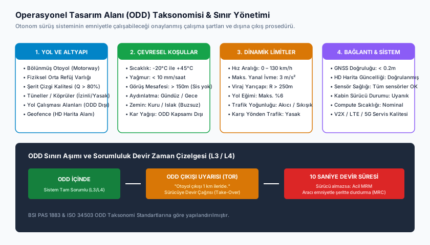
- Analyze the ODD taxonomy across four systematic dimensions (Roadway Type, Environmental Conditions, Speed Range, Traffic/Temporal Conditions) per BSI PAS 1883 and ISO 34503.
- Evaluate why operating outside an ODD is not a 'less capable' mode but an unvalidated/undefined behavior regime.
- Understand how ODD boundaries are enforced in practice through geofencing, real-time environmental sensing, and speed thresholds.
- Deconstruct Mercedes-Benz Drive Pilot's narrow certified ODD as a concrete real-world engineering case study.
AD-16 — Operational Design Domain (ODD): Definition, Taxonomy and Boundaries
FACT — SAE J3016 defines the Operational Design Domain (ODD) as “the specific operating conditions under which a given driving automation system, or feature thereof, is specifically designed to function” — including roadway type, geographic location, speed range, lighting, weather, traffic, and road regulations. That definition sounds brief, but it is arguably the second-most important concept in automotive safety engineering after the Dynamic Driving Task (DDT) introduced in AD-02 — because asking “how well does this automation system perform” is meaningless on its own; the only meaningful question is “under which validated conditions does it perform.”
In this lesson, we treat ODD as an engineering discipline in its own right:
- The Formal Definition of ODD and Why It Underpins Everything Above Level 0
- Taxonomy Dimension 1 — Roadway Type and Infrastructure
- Taxonomy Dimension 2 — Environmental Conditions (Weather, Lighting, Road Surface)
- Taxonomy Dimension 3 — Speed Range: Both a Lower AND an Upper Bound
- Taxonomy Dimension 4 — Traffic and Temporal Conditions
- The Critical Safety Principle: ODD Exit = Undefined Behavior, NOT a “Reduced Capability” Mode
- Enforcing ODD Boundaries in Practice: Geofencing, Sensing, Thresholds
- Case Study: Mercedes-Benz Drive Pilot’s Real-World ODD
1. The Formal Definition of ODD and Why It Underpins Everything
In AD-02 we decomposed the DDT (Dynamic Driving Task) into operational, tactical, and strategic layers. ODD is the envelope defining where, when, and under what physical conditions that DDT execution is actually valid. Formally, ODD can be expressed as the Cartesian product of several independent condition sets:
Here is the set of permitted roadway types, the set of permitted weather conditions, the set of permitted lighting states, the speed range, and the set of permitted traffic/temporal conditions. The vehicle’s actual state at any instant, , is inside the ODD only if it lies within every single component simultaneously — exiting even one dimension (say, exceeding the speed bound) is sufficient to leave the ODD entirely.
FACT — The ODD concept is technically applicable from SAE Level 0 upward, but its practical weight begins at Level 1: at Level 0 there is no automation feature, so “under which conditions does it operate” is a moot question. From Level 1 onward (e.g., Adaptive Cruise Control), every single automation feature has its own ODD — and a manufacturer’s safety case is, mathematically, always framed as “this system is safe within ODD X,” never as an unconditional “it is safe” claim.
2. Taxonomy Dimension 1: Roadway Type and Infrastructure
BSI PAS 1883 and ISO 34503 place ODD into a standardized taxonomy tree. The first dimension is the physical road infrastructure the system may operate on:
| Sub-Dimension | Example Values | Why It Matters |
|---|---|---|
| Roadway class | Divided motorway, urban arterial, rural two-lane road | Traffic density, junction frequency, and opposing-traffic collision risk differ fundamentally by class |
| Division | Physically divided highway with barrier vs. undivided two-way road | On undivided roads, head-on collision risk with oncoming traffic exists; on divided highways, it does not |
| Geofence / route restriction | Pre-mapped, certified specific corridors (HD map) | The system is only proven safe on thoroughly validated routes; an unmapped side road is out of ODD |
| Lane marking quality | Fresh, high-contrast lane paint vs. faded/absent | Lane-keeping algorithms become unreliable without a visual reference |
| Road geometry | Maximum grade, minimum curve radius, ramp/junction density | Dynamic control models are validated for a specific geometric envelope |
INTERPRETATION — The roadway dimension is usually enforced physically via geofencing (see §7): the system only activates within a pre-approved HD map polygon. This exposes the gap between “theoretically capable on this road class” and “proven, kilometer-by-kilometer, on this specific audited road” — nearly all production L3 systems use the latter, much narrower definition.
3. Taxonomy Dimension 2: Environmental Conditions
Weather, lighting, and road surface conditions connect directly to the sensor physics covered in AD-04 and AD-05 — every sensor’s reliability has been measured and validated below/above a specific environmental threshold, so ODD expresses those thresholds as concrete numbers:
| Sub-Dimension | Typical ODD Threshold | Physical Rationale |
|---|---|---|
| Precipitation intensity | Light rain < 2.5–5 mm/hr; heavy downpour/hail out of ODD | Water film on camera lens, LiDAR return scattering in fog/rain droplets (AD-05) |
| Visibility distance | > 150–200 m | Camera/LiDAR object detection is validated for a minimum visibility distance |
| Lighting | Daylight / dusk / well-lit night road — some systems daylight-only | Camera dynamic range and classification models are separately trained/validated per light condition |
| Road surface | Dry/wet asphalt; ice/snow typically out of ODD | Friction coefficient () changes invalidate braking-distance calculations |
| Temperature range | e.g., −20°C to +45°C | Sensor calibration and battery/actuator performance are temperature-dependent |
| Crosswind | Upper limit on lateral wind speed | High crosswind can exceed the validated operating band of the lane-keeping controller |
WARNING — These thresholds are rarely binary (“raining / not raining”) — they are defined as sub-thresholds, such as “light rain ONLY.” A system may be validated for light rain yet completely untested for moderate/heavy rain; a crude “rain sensor triggered yes/no” logic that cannot distinguish the intermediate state loses the ODD definition’s granularity and creates false confidence.
4. Taxonomy Dimension 3: Speed Range — Both a Lower and Upper Bound
CRITICAL — The most commonly misunderstood aspect of ODD is that many systems’ speed constraint is not a one-sided upper limit but a two-sided band with both a floor and a ceiling. Two typical architectures make this explicit:
- Traffic Jam Pilot (typically L3): The system operates only below a threshold speed (, e.g., ) — because the algorithm is validated for close-following and frequent stop-and-go at very low speed; the same following logic gives no guaranteed safe braking distance at higher speed.
- Highway Pilot (typically L2/L3): The system operates only above a threshold speed (, e.g., ) — because at low speed, urban intersection/pedestrian/cyclist interactions are a scenario class the highway perception model was never trained on.
These two architectures’ speed bands may complement each other but need not overlap — if a vehicle has both traffic-jam-pilot and highway-pilot features, the gap between them ( to ) may have no automation active at all, returning full driving responsibility to the human. This can create a confusing “automation gap” in the user experience, and HMI design (as we’ll see in AD-17) must communicate it unambiguously.
ODD Bands Along the Speed Axis (Example: Two Functions):

0 km/h                    v_max^TJP        v_min^HWP           v_max^HWP
  |──── Traffic Jam Pilot ─────|            |──── Highway Pilot ────|
  |          (TJP)             |    GAP     |         (HWP)         |
  |         ACTIVE             |  (Driver)  |        ACTIVE          |
  └─────────────────────────────────────────────────────────────────▶ speed
                              (e.g. 60)   (e.g. 60-80)
5. Taxonomy Dimension 4: Traffic and Temporal Conditions
The final dimension is not the road’s static geometry or the weather, but the live dynamic traffic context:
- Construction/work zones: Temporary lane narrowing, cone/barrier layouts, human traffic controllers — geometry that changes in real time and is absent from the HD map. Most systems auto-exit ODD upon detecting a work zone.
- School zones: Variable speed limits, elevated expected pedestrian density, temporal restriction tied to school hours.
- Presence of emergency vehicles: When flashing lights/sirens are detected (see AD-06’s perception stack), many jurisdictions legally require a lane change/slowdown response — this behavior must be defined and validated within the ODD, or the system must disengage.
- Traffic density regime: Free-flowing vs. stop-and-go congested traffic require different following-distance/acceleration profiles; some systems are validated for only one of the two.
EXAMPLE — Consider a highway pilot system: roadway type (divided motorway ✓), weather (clear ✓), speed (95 km/h, in range ✓) — three of four dimensions are within ODD. But the moment construction cones appear ahead, the fourth dimension (traffic/temporal conditions) instantaneously exits the ODD. Because ODD compliance is a single, indivisible conjunction, the system must disengage even though the other three dimensions remain fully compliant — partial compliance does not count as being within ODD.
6. Critical Safety Principle: ODD Exit Means Undefined Behavior
CRITICAL — This is the single most important sentence in this lesson: a system operating outside its ODD is not a “less capable” version of itself — its behavior is unvalidated and undefined. This distinction may sound semantic, but it is the foundation of safety engineering.
Why? Because every layer of a modern ADAS/ADS stack — perception models, tracking filters, planning heuristics, control gains — has been trained and/or derived under a specific data distribution and/or a specific set of physical assumptions. ISO 21448 (SOTIF — Safety of the Intended Functionality) formalizes exactly this: a system’s performance limitations relate not only to hardware/software faults but also to the scenario space it has never seen or validated. Exiting the ODD means entering precisely that “unknown-unsafe” region:
SOTIF Scenario Space Classification (ISO 21448):

  ┌─────────────────────────────────────────────┐
  │              ALL POSSIBLE SCENARIOS           │
  │  ┌───────────────────────────────────────┐   │
  │  │            ODD (Defined Space)          │   │
  │  │   ┌─────────────┐                      │   │
  │  │   │  Known-      │   Known-             │   │
  │  │   │  Safe        │   Unsafe             │   │
  │  │   │  (Validated) │   (Tested, has        │   │
  │  │   │              │    mitigation)        │   │
  │  │   └─────────────┘                      │   │
  │  └───────────────────────────────────────┘   │
  │                                                │
  │     OUTSIDE ODD = "Unknown" Region            │
  │     (Never characterized as safe or           │
  │      unsafe — behavior is undefined)          │
  └─────────────────────────────────────────────┘
A concrete example: a highway pilot’s object detection neural network may have been trained and validated on millions of kilometers of highway imagery. If that network is suddenly run on an icy mountain road or in a dust storm — even though it may appear to “still function” — there is no statistical guarantee whatsoever about the correctness of its output. The system might misclassify an object, entirely miss an obstacle, or trigger an unnecessary emergency stop; none of these is “expected, somewhat worse performance” — all are wholly outside the validation envelope and therefore unpredictable.
This is why ODD-exit detection and enforced fallback (the subject of AD-17) is not an optional “nice to have” feature but a hard safety requirement: the system must know at every instant where it stands relative to its own validation boundary, and must safely relinquish control the moment it approaches or crosses that boundary.
7. Enforcing ODD Boundaries in Practice
While the ODD definition is a paper taxonomy, a real vehicle must continuously, low-latency monitor compliance with that definition at runtime. There are three primary enforcement mechanisms:
7.1 Geofencing (Geographic Boundary Enforcement)
The roadway/route dimension is typically enforced via a pre-approved HD map polygon. The vehicle’s real-time GNSS-RTK position (see AD-04 §6) is checked against that polygon using a point-in-polygon test. Crossing outside the polygon instantly triggers an ODD violation.
7.2 Real-Time Environmental Sensing
Weather/visibility/road-surface conditions cannot be known from a static map — the vehicle must continuously estimate them with its own sensors: rain sensors, visibility-distance estimation derived from camera image contrast/blur analysis, road-surface friction estimation derived from wheel slip ratio.
7.3 Speed Threshold Monitoring
The simplest but most frequently triggered mechanism: the instant the vehicle’s speed leaves the band, the system either cannot engage or (if already engaged and the bound is exceeded) begins its disengagement process.
Together, these three mechanisms produce a single logical indicator of whether the vehicle is within ODD at any moment:
This product structure is deliberate: the entire expression collapses to zero the instant a single indicator is zero — meaning exiting even one of the four dimensions is sufficient, with no tolerance for “three dimensions fine, one missing, that’s acceptable.”
ODD Boundary Monitoring Runtime Loop:

  [GNSS+Map]     [Speed Sensor]   [Camera/Rain Sens.]   [Traffic/Time Info]
        │              │                │                    │
        ▼              ▼                ▼                    ▼
   Geofence Test   Speed Band Test  Environment Test     Context Test
        │              │                │                    │
        └──────────────┴────────┬───────┴────────────────────┘
                                 ▼
                      InODD(x_t) = PRODUCT
                                 │
                 ┌───────────────┴───────────────┐
                 ▼                                ▼
            1 (Within ODD)                  0 (Outside ODD)
                 │                                │
         Automation Continues          → AD-17: Fallback / MRM Initiated
INTERPRETATION — In practice, manufacturers typically approach the boundary not “suddenly” but through a preceding boundary warning zone — for example, a driver takeover request may be issued 2 km ahead of a geofence boundary, or as soon as weather conditions trend toward the threshold. This produces a predictable, staged transition instead of an abrupt ODD exit — we’ll examine this escalation logic in detail in AD-17.
8. Case Study: Mercedes-Benz Drive Pilot
ASSUMPTION — The parameters below are based on Mercedes-Benz’s publicly disclosed DRIVE PILOT information and regulatory approval processes (Germany, under UNECE R157-based type approval; U.S. state approvals in Nevada/California); the exact current list of covered highway kilometers and the speed threshold vary by manufacturer, model year, and jurisdiction, and have been expanded over time — exact current coverage should be verified against manufacturer documentation.
DRIVE PILOT, as one of the first production systems certified for conditional (SAE Level 3) automation, is a concrete illustration of just how narrow and precise an ODD can be:
| Taxonomy Dimension | DRIVE PILOT’s ODD (approximate, initial certification stage) |
|---|---|
| Roadway type | Pre-approved, HD-mapped, specific divided highway segments with a physical median (geofence) |
| Environment | Daylight only, clear/dry weather — heavy rain, snow, fog out of ODD |
| Speed | (typical at initial certification; later expansion has been planned/pursued) |
| Traffic | Dense/stop-and-go highway traffic (requires a lead vehicle to follow) — construction zones, accident scenes out of ODD |
| Other | The system permits the driver to look away from the road but not to fall asleep (see the AD-18 DMS connection) |
INTERPRETATION — DRIVE PILOT’s narrowness is not a weakness but a deliberate engineering and regulatory strategy: at L3, liability sits with the system (AD-02, AD-17), so the manufacturer keeps every dimension conservatively narrow, preferring to keep the “known-safe” region (see the §6 diagram) as small as possible but 100% validated. Over time the ODD coverage (higher speed, more road segments, additional weather conditions) is expanded incrementally — each expansion is a separate certification effort requiring its own validation of the newly added sub-domain; it does not grow “automatically.”
Frequently Asked Questions (FAQ)
Q: Does a system stop immediately the moment it exits its ODD?
INTERPRETATION — No, most production systems implement a staged transition rather than an abrupt stop: first a driver takeover request, and if unanswered, a system-executed Minimal Risk Manoeuvre (MRM). We cover this mechanism in full detail in AD-17.
Q: Is ODD a static document, or does the vehicle compute it in real time?
FACT — Both: the definition of the ODD (which roadway types, which speed range, which weather thresholds) is a static specification fixed during development/certification. But whether the vehicle is actually within that ODD at a given moment (the InODD indicator in §7) is continuously recomputed in real time from live sensor/map data on every driving instant.
Q: Can an expanded ODD (e.g., a higher speed limit) arrive via a software update?
ASSUMPTION — Depending on the manufacturer and jurisdiction, yes, this is generally possible via OTA (over-the-air) software updates — but every expansion requires the newly added sub-domain to pass its own separate safety validation/certification process; this is a strict legal/technical procedure that varies by manufacturer and by country.
Summary
- ODD (Operational Design Domain), per SAE J3016, is the full set of operating conditions under which a driving automation feature is designed to function safely; every automation feature (from Level 1 onward) has its own ODD.
- The ODD taxonomy splits into four systematic dimensions: Roadway Type/Infrastructure, Environmental Conditions, Speed Range (which can be both lower- and upper-bounded), and Traffic/Temporal Conditions.
- ODD is the Cartesian product and logical AND of these dimensions — exiting even one dimension is sufficient to exit the system’s entire ODD.
- Operating outside the ODD is not a “reduced capability mode” but entering an unvalidated/undefined behavior regime (the “unknown” scenario region within the ISO 21448/SOTIF framework) — which is why ODD-exit detection and enforced fallback is a hard safety requirement.
- ODD boundaries are continuously monitored in practice via geofencing, real-time environmental sensing, and speed threshold checks; approaching a boundary is usually managed through a preceding warning band, producing a staged transition rather than an abrupt cutoff.
- Mercedes-Benz DRIVE PILOT is a real-world example of a deliberately narrow L3 ODD (specific highway segments, ≤60 km/h, daylight, clear weather); coverage expands over time through separate certification steps.
Sources and Verification Note
The ODD definition and taxonomy presented in this lesson are grounded in SAE J3016 terminology, the BSI PAS 1883 and ISO 34503 ODD taxonomy standards, and the ISO 21448 (SOTIF) framework. Specific parameters attributed to Mercedes-Benz DRIVE PILOT are based on publicly available manufacturer/regulatory disclosures and are marked as ASSUMPTION; exact current coverage should be verified against manufacturer documentation and the relevant jurisdiction’s regulatory approval texts.
Next Lesson
- AD-17 — Fallback Strategies, MRM and Minimal Risk Condition (MRC): We detail what the system does once it reaches or exceeds the ODD boundary defined in this lesson — DDT Fallback, the distinction between a Minimal Risk Manoeuvre (MRM) and a Minimal Risk Condition (MRC), and the staged warning/takeover escalation architecture.
Technical Diagrams
Quiz
What does the Operational Design Domain (ODD) fundamentally specify?
ODD establishes the operational boundary conditions for automated driving functions.
Which is an example of an operational boundary condition within a Highway Pilot ODD?
Divided roadway infrastructure and velocity limits are foundational ODD attributes.
How does an active ODD monitor react upon detecting heavy snow accumulation?
Snow accumulation violates certified visibility and friction bounds, prompting an immediate fallback transition.
What is the primary scope of the BSI PAS 1883 international standard?
BSI PAS 1883 provides a standardized taxonomic framework for defining ODDs.
What action does an ADS execute when approaching the spatial edge of its ODD (e.g. 1 km from highway exit)?
Advance boundary detection allows the system to schedule a graceful, staged Take-Over Request.
Glossary
| English Term | Definition |
|---|---|
| Operational Design Domain (ODD) | The specific operating conditions (roadway types, speed bounds, weather, lighting, geography) under which a driving automation system is certified and designed to function safely. |