
- Show, using bandwidth/compute-power math, why traditional distributed ECU architecture became a bottleneck for ADAS/AD workloads.
- Relate centralized compute (HPC) architecture to how it enables the early/deep sensor fusion covered in AD-07.
- Model zonal E/E architecture's physical, zone-based organization and its wiring-harness savings.
- Evaluate why Automotive Ethernet standards (10BASE-T1S through Multi-Gig) and TSN partially displace CAN, and why CAN/CAN-FD does not disappear entirely.
AD-29 — Next-Generation Architectures: Centralized Compute, Zonal E/E and Ethernet
FACT — A single 8-megapixel ADAS camera produces roughly of uncompressed raw pixel data per second. A classic CAN bus, by contrast, tops out at (a few Mbps in practice with CAN-FD) — meaning the raw output of ONE camera is THOUSANDS of times larger than classic CAN’s capacity. This single number summarizes why the automotive industry has had to fundamentally rethink decades of distributed E/E architecture.
In this lesson, you will learn:
- Why Traditional Distributed E/E Architecture Became a Bottleneck
- The Three-Stage Evolution: Distributed → Domain → Zonal
- Centralized Vehicle Compute (HPC) Architecture
- Zonal E/E Architecture: Organized by Zone, Not by Function
- Why Ethernet: CAN’s Physical Limits vs. Packet-Switched Networking
- Automotive Ethernet Standards and TSN (Time-Sensitive Networking)
- Raw Sensor Data Transport: SerDes and MIPI A-PHY
- Hybrid Architecture: Why CAN/CAN-FD Doesn’t Disappear Entirely
- Case Study: An Industry Mid-Transition
1. Why Traditional Distributed E/E Architecture Became a Bottleneck
A conventional vehicle’s Electrical/Electronic (E/E) architecture is built on a one ECU per function philosophy: one ECU for ABS, another for power windows, another for adaptive cruise control. Production vehicles can exceed 100 such ECUs, and premium-segment vehicles can exceed 150 — each connected by kilometers of CAN/LIN wiring.
This architecture becomes a dual bottleneck for ADAS/AD compute workloads:
- Bandwidth bottleneck: The camera, radar, and LiDAR sensors covered in AD-04 — ADAS Sensors: Camera, Radar, LiDAR, Ultrasonic, GNSS and IMU each generate hundreds of megabits to several gigabits of raw data per second. Classic CAN’s , and CAN-FD’s few-Mbps practical ceiling, cannot carry the output of even a single high-resolution sensor.
- Compute bottleneck: In a distributed architecture, each ECU performs a LIMITED task with its own small microcontroller (e.g., “extract an object list from this radar’s raw data”). But modern deep-learning-based perception/planning, as covered in AD-07 — Sensor Fusion: Early, Late and Deep Fusion Architectures, requires COMBINING raw sensor data at early/deep layers — which mandates a single, powerful centralized compute platform in place of dozens of scattered small processors.
CRITICAL — These two bottlenecks reinforce each other: performing early/deep sensor fusion requires gathering raw data in ONE place (the compute argument), but gathering raw data in one place also requires a high-bandwidth backbone (the bandwidth argument). Classic distributed architecture cannot satisfy either — which is why the architectural shift is not an optional modernization but a technical PRECONDITION for ADAS/AD.
2. The Three-Stage Evolution: Distributed → Domain → Zonal
Vehicle E/E architectures pass through three major evolutionary stages:
[ 1. Distributed Legacy ]         [ 2. Domain-Oriented ]            [ 3. Zonal + Central Compute ]

 +----+  +----+  +----+  +----+      +-------------------+              +--------------------+
 |ECU1|  |ECU2|  |ECU3|  |ECUn|      |  ADAS Domain      |              |   CENTRAL COMPUTE  |
 +----+  +----+  +----+  +----+      |  Controller       |              |   (HPC / "Brain")  |
   |       |       |       |         +-------------------+              +--------------------+
  (100+ discrete microcontrollers,           |                              | (Multi-Gig Ethernet)
   each with its own wiring run)     (Functional silos:          +-----------------+-----------------+
  - Heavy, long wiring harnesses      ADAS / Cockpit / Body)     |                 |                 |
  - Low-bandwidth CAN/LIN                     |                Front Zone      Left Zone       Rear Zone
                                       Wiring still runs           Gateway       Gateway         Gateway
                                       cross-vehicle                  |             |                |
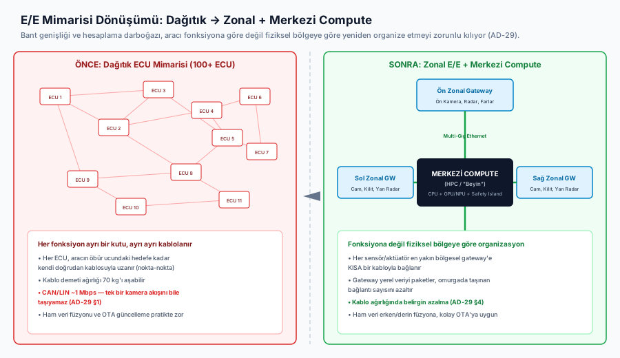
S1 S2 Act S3 S4 Act S5 S6 Act- Distributed Architecture: A separate box per function. Harness mass can exceed 70 kg, and OTA-updating the whole system is close to impractical.
- Domain Architecture: Functions are grouped into logical domains (ADAS Domain, Infotainment Domain, Body Domain). A step forward, but wiring still runs the full length of the vehicle from sensor to domain controller.
- Zonal Architecture: Grouping by physical LOCATION (Front-Left, Front-Right, Rear zone). Each zone’s gateway aggregates all local sensors/actuators, packetizes the data, and forwards it over a single high-speed Ethernet backbone to central compute.
3. Centralized Vehicle Compute (HPC) Architecture
A central compute platform (example class: the NVIDIA DRIVE family, the Qualcomm Snapdragon Ride family) unifies logic that used to be scattered across dozens of separate ECUs onto a single powerful SoC (System-on-Chip):
- Heterogeneous core structure:
- CPU cluster — general-purpose OS, path planning, and decision logic.
- GPU/NPU accelerator — deep-learning perception and the early/deep fusion models covered in AD-07; on the order of hundreds to thousands of TOPS (int8) of compute.
- Safety Island — separate, isolated, hardware lock-step real-time cores operating at ASIL-D that guarantee a minimal risk maneuver (see AD-17 — Fallback Strategies, MRM and Minimal Risk Condition) even if the primary AI stack crashes.
- Hardware-enforced virtual isolation (Hypervisor): Safety-critical software (e.g., the instrument cluster) and infotainment run on the same SoC but in hardware-isolated virtual machines — a crash in one does not affect the other.
Central compute is the direct answer to the second bottleneck described above (compute power): early/deep sensor fusion, impossible in a distributed architecture, becomes possible once raw data reaches a single chip.
4. Zonal E/E Architecture: Organized by Zone, Not by Function
The core idea of zonal architecture is simple, but its consequences run deep: organize the vehicle’s electrical architecture by physical ZONE rather than by FUNCTION.
In a classic/domain architecture, an actuator like a “front-left headlight” runs its own wiring — wherever it physically sits in the vehicle — all the way to its functional ECU (the Body Domain Controller). In a zonal architecture, that same headlight instead connects via a short cable to the Front-Left Zonal Gateway physically nearest to it; ALL sensors/actuators in that zone (headlights, window motors, nearby cameras, ultrasonic sensors) converge on the same gateway, which forwards them to central compute over a single high-speed link.
Components Aggregated by a Zonal Gateway (Front-Left Zone Example):

  Headlight ──┐
  Window Motor ──┤
  Near-Field Camera ──┼──▶ [ FRONT-LEFT ZONAL GATEWAY ] ──(Multi-Gig Ethernet)──▶ [ CENTRAL COMPUTE ]
  Ultrasonic x2 ──┤
  Door Lock ──┘
The gain from this reorganization is directly geometric: every component now connects to a regional gateway a few centimeters to a few meters away, rather than to a controller on the opposite end of the vehicle. The result is a marked reduction in total wiring LENGTH and therefore mass — a meaningful savings even compared to a pure star topology connecting every component directly to central compute, because the zonal gateway performs local aggregation/packetization, reducing the number of individual links carried on the backbone.
FACT — A figure frequently cited in industry reporting is that migrating to a zonal architecture can reduce wiring-harness mass significantly (varying by manufacturer and platform, roughly on the order of tens of kilograms). For an electric vehicle, this mass savings translates directly into range; shorter, more standardized cable segments also ease robotic assembly on the production line. Exact figures vary substantially by manufacturer and platform.
5. Why Ethernet: CAN’s Physical Limits vs. Packet-Switched Networking
CAN (Controller Area Network) was designed in the 1980s for short, low-bandwidth control messages (e.g., “brake pedal 40% depressed,” “engine speed 2400 rpm”) — a few bytes per message, broadcast-based, priority arbitration. This design philosophy is fundamentally mismatched with the continuous, high-volume streaming data (camera frames, LiDAR point clouds) that ADAS/AD requires:
- CAN’s data field is capped at 8 bytes per message (classic CAN) or 64 bytes (CAN-FD) — splitting a video frame into CAN messages is impractical.
- CAN is broadcast-based (every node on the bus sees every message); efficient for small control messages, but wasteful for point-to-point, high-volume streams.
Automotive Ethernet, by contrast, is inherently a packet-switched network — data is routed in addressed packets, over only the relevant link. This is a natural fit for streaming sensor data (continuous, high-volume, point-to-point):
INTERPRETATION — This is not a “CAN bad, Ethernet good” story — the two were designed for different problems. CAN remains an excellent match for deterministic, low-latency, SHORT control messages on the order of microseconds (see §8). Ethernet solves a problem CAN was never designed for — continuous, high-volume sensor streaming. The architecture the industry is converging on is not CAN being COMPLETELY replaced by Ethernet, but a HYBRID network where each protocol is used for the task it excels at.
6. Automotive Ethernet Standards and TSN (Time-Sensitive Networking)
| Standard | Bandwidth | Cable Type | Typical Automotive Use |
|---|---|---|---|
| 10BASE-T1S | 10 Mbps | Single twisted pair | Low-speed body sensors, applications replacing legacy LIN |
| 100BASE-T1 | 100 Mbps | Single twisted pair (UTP) | Surround-view cameras, telematics |
| 1000BASE-T1 | 1 Gbps | Shielded single twisted pair (STP) | High-resolution LiDAR streams, zonal gateway backbone |
| Multi-Gig (IEEE 802.3ch) | 2.5 / 5 / 10 Gbps | Shielded STP / coaxial | Zonal gateway ↔ central compute high-speed backbone |
TSN (Time-Sensitive Networking)
Standard commercial Ethernet operates on a “best-effort” basis — it offers no latency guarantee, and packets can be delayed under network congestion. This is unacceptable for time-critical ADAS messages such as emergency braking. The TSN protocol suite gives Ethernet deterministic behavior:
- IEEE 802.1AS (gPTP): Synchronizes every sensor/ECU clock in the vehicle to sub-microsecond precision — a precondition for the sensor fusion covered in AD-07 (fusion is unreliable without temporal alignment).
- IEEE 802.1Qbv (Time-Aware Shaper): Reserves time slots on the network for critical messages; braking messages pass through without waiting even while infotainment data is on the wire.
7. Raw Sensor Data Transport: SerDes and MIPI A-PHY
An 8-megapixel ADAS camera produces roughly of raw pixel data per second. Compressing this data introduces visual artifacts and adds codec decoding latency — an undesirable trade-off for a system sensitive to detection latency. For this reason, dedicated SerDes (Serializer/Deserializer) physical layers carry uncompressed raw data:
- MIPI A-PHY and ASA (Automotive SerDes Alliance): Standards that stream raw CSI-2 pixel data straight from the sensor lens over a single coaxial cable, over distances up to 15 meters, at data rates on the order of 16 Gbps, directly into central compute’s memory.
8. Hybrid Architecture: Why CAN/CAN-FD Doesn’t Disappear Entirely
As covered in §5, CAN’s weakness (low bandwidth) is simultaneously its strength in a specific task class: deterministic, short, safety-critical control messages on the order of microseconds.
- For low-data-volume but ULTRA-low-latency, high-reliability messages — brake commands, steering-angle commands — CAN/CAN-FD’s simple, well-understood, decades-proven architecture remains the preferred choice.
- Ethernet’s packet-switched nature and more complex protocol stack, even made deterministic via TSN, does not yet carry the same depth of verification/certification history that CAN’s simplicity does.
WARNING — The core takeaway of this lesson should not be read as “Ethernet is replacing CAN,” but as “Ethernet is taking on the job CAN could NEVER do (high-volume sensor streaming), while CAN continues doing the job it’s good at (low-volume, ultra-reliable control).” The result, in most modern zonal architectures, is a hybrid network topology where CAN-FD and Ethernet operate TOGETHER on different tasks — an architecture that has fully abandoned CAN is not common current industry practice.
9. Case Study: An Industry Mid-Transition
ASSUMPTION — The manufacturer-specific architectural approaches in this section are based on publicly available technical press statements and industry conference presentations; the FULL zonal/central architecture implementation details for a specific manufacturer’s specific model year have not been verified against official technical documentation. These examples are conceptual illustrations — consult the manufacturer’s own technical publications for precise, current architecture.
The automotive industry is IN THE MIDDLE of this transition — it is not a universally completed transformation:
- Some newer platforms have brought a zonal-gateway architecture built around a central compute SoC into production; this is generally seen on newer-generation electric vehicle platforms and clean-sheet designs.
- Many manufacturers are in an INTERMEDIATE stage of transition: domain architecture (separate but consolidated controllers such as an ADAS Domain Controller and a Body Domain Controller) remains common, with a full zonal transformation happening gradually alongside platform refreshes.
- Models built on legacy platforms may retain a distributed/domain hybrid architecture for longer, for reasons of backward compatibility and cost.
INTERPRETATION — It would be incorrect to read this lesson as “all production vehicles have now moved to zonal architecture.” The accurate framing is: this is an architectural DIRECTION the industry is ACTIVELY moving toward — the bandwidth and compute demands of ADAS/AD workloads make this direction technically necessary — but the speed and depth of the transition varies considerably by manufacturer and platform.
Frequently Asked Questions (FAQ)
Q: Does moving to a zonal architecture consolidate all ECUs into a single central computer?
FACT — Not exactly. Central compute consolidates high-level perception/planning/decision logic, but zonal gateways still handle regional aggregation/routing — and are themselves small controllers capable of local processing. Additionally, as covered in §8, low-level safety-critical control remains on a separate CAN/CAN-FD layer; “a single central computer with no distributed processing at all” is not an accurate description.
Q: Why is perception now done in central compute rather than inside smart cameras?
INTERPRETATION — Legacy systems used “smart cameras” that performed object detection with their own small processor and sent only an object list. But the modern deep fusion models covered in AD-07 require combining raw pixel data with raw radar/LiDAR data at an EARLY layer — which requires sensors to be “dumb” endpoints that send raw data, and central compute to be a powerful “brain” that performs all the fusion.
Q: What happens if central compute fails?
CRITICAL — At higher automation levels (L4/L5), a single central computer is not relied upon; dual/redundant HPC architectures are used, and if the primary SoC fails, the secondary takes over (fail-operational). Additionally, the Safety Island covered in §3 is an independent, hardware lock-step subsystem that guarantees a minimal risk maneuver (see AD-17) even if the primary AI stack fails completely.
Summary
- The raw data rate of a single high-resolution camera/LiDAR sensor exceeds classic CAN’s capacity by thousands of times — mathematical proof that modern ADAS/AD compute workloads are fundamentally incompatible with distributed ECU architecture.
- The industry is undergoing a three-stage evolution — Distributed → Domain → Zonal; zonal architecture organizes the vehicle by physical zone rather than by function.
- Central Compute (HPC) unifies logic that used to sit across dozens of distributed ECUs into a single powerful SoC and enables the early/deep sensor fusion covered in AD-07; a separate Safety Island guarantees a minimal risk maneuver even if the primary AI fails.
- Zonal gateways aggregate regional sensors/actuators, reducing wiring length/mass; Automotive Ethernet (10BASE-T1S through Multi-Gig) and TSN carry the high-volume, deterministic sensor streaming CAN was never designed for.
- CAN/CAN-FD remains strong for low-volume but ultra-reliable safety-critical control messages — the result is not CAN being fully replaced by Ethernet, but a hybrid architecture where both operate together.
- This transition is active and ongoing across the industry; there is no single universally completed architecture, and the speed and depth of transition varies by manufacturer.
Sources and Verification Note
This lesson draws on the IEEE 802.3 Automotive Ethernet standards family, MIPI A-PHY/ASA (Automotive SerDes Alliance) specifications, AUTOSAR Adaptive Platform documentation, the Bosch CAN/CAN-FD specification, and SAE J3016 terminology. The manufacturer-specific architectural transition examples in §9 are based on publicly available technical press and industry conference sources and are marked ASSUMPTION; consult a given manufacturer’s official technical documentation for CURRENT, FULL architectural detail.
Next Lesson
- AD-30 — SAE Levels in Practice: Worked Examples and Comparative Liability Analysis: In the academy’s closing lesson, we synthesize the automation levels operating atop the hardware/data architecture covered in this lesson through real-world scenarios and a comparative liability analysis.
Technical Diagrams
Quiz
What is the most immediate physical engineering benefit of transitioning to a Zonal E/E vehicular architecture?
Zonal architectures aggregate local I/O onto regional gateways, slashing tens of kilograms of wire harness mass and streamlining robotic manufacturing.
What is the primary function of the integrated 'Safety Island' within a Central HPC System-on-Chip?
Safety Islands feature isolated ASIL-D lock-step cores capable of executing deterministically to maintain vehicle stability during high-level OS crashes.
What is the core technical justification for deploying Time-Sensitive Networking (TSN) over Automotive Ethernet backbones?
TSN overrides stochastic Ethernet queuing via scheduled traffic shaping (IEEE 802.1Qbv), guaranteeing deterministic latency for critical chassis commands.
Which standardized SerDes protocol is engineered to transport uncompressed raw high-resolution (8 MP) automotive camera pixels directly to central compute?
MIPI A-PHY and ASA represent standardized automotive SerDes specifications delivering multi-gigabit uncompressed raw pixel streams directly to GPU memory.
Glossary
| English Term | Definition |
|---|---|
| Zonal E/E Architecture | A modern vehicle electrical/electronic architecture approach organizing the E/E system by physical ZONE (front, rear, left, right) rather than by function, with a zonal controller in each area aggregating local sensors/actuators and connecting to central compute over a high-speed backbone — reduces wiring harness complexity/weight. |
| Automotive Ethernet | A family of packet-switched in-vehicle communication standards offering far higher bandwidth (100 Mbps to multi-Gbps) than traditional CAN bus — enables carrying high-volume sensor streams (camera/LiDAR) required by centralized/early-fusion architectures. |