
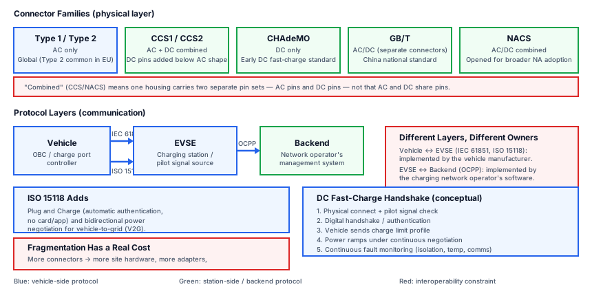
- List the main charging connector families (Type 1/2, CCS1/2, CHAdeMO, GB/T, NACS) and their AC/DC scope.
- Distinguish the roles of IEC 61851, ISO 15118, DIN SPEC 70121, and OCPP.
- Explain why vehicle-side and charger-backend protocols occupy different layers and must not be confused.
- Describe, conceptually, the handshake sequence between a vehicle and a DC fast charger.
- Explain why connector fragmentation is a real interoperability and infrastructure cost, not just a naming inconvenience.
EV-37 — Charging Standards
ASSUMPTION — Charging standards and their regional adoption evolve continuously; this lesson introduces the connector families and protocol layers conceptually, without claiming any specific current market-share figures, power ratings, or regional mandates as fact. Verify current specifics against
data/regulations/or current standards-body sources before relying on them.
1. Why Charging Needs More Than “a Plug”
Charging an EV looks, from the outside, like plugging in an appliance, but it actually requires a live negotiation between two independent electrical systems that were designed and manufactured by different companies, possibly years apart, with no prior knowledge of each other. The vehicle must tell the charging equipment what it can safely accept (voltage range, maximum current, connector type), the charging equipment must tell the vehicle what it can supply, and both sides must continuously monitor the connection for faults throughout the session — because unlike a household plug, an EV charging connector can carry currents and, in the DC fast-charging case, voltages capable of causing serious harm if mismanaged. This is why charging is standardized at both the physical connector level and the communication protocol level, and why the two must be understood separately.
2. Connector Families
Connectors differ primarily by region and by whether they carry AC, DC, or both through the same physical interface:
| Connector | Type | Notes |
|---|---|---|
| Type 1 / Type 2 | AC | Common single-phase (Type 1) and single/three-phase (Type 2) AC charging connectors |
| CCS1 / CCS2 | Combined AC + DC | Adds DC pins below the AC connector shape, so one port handles both AC and DC fast charging |
| CHAdeMO | DC | An early DC fast-charging standard, historically associated with some Japanese manufacturers |
| GB/T | AC/DC | China’s national standard, with separate AC and DC connector variants |
| NACS | AC/DC | Originated as a single manufacturer’s proprietary connector, later opened and adopted more broadly in North America |
FACT — A “combined” connector like CCS does not mean AC and DC use the same pins — it means the same physical housing carries a set of AC pins for slower charging and a separate set of DC pins for fast charging, so the vehicle and station simply use whichever pin set matches the negotiated charging mode.
3. Communication Protocol Layers
Beneath the visible connector, several distinct protocol layers do different jobs, and conflating them is one of the most common sources of confusion in this topic. IEC 61851 defines the most basic layer: a pilot signal (a simple duty-cycle-modulated control signal) that tells the vehicle the maximum current available and lets the vehicle and station confirm a safe connection state before power flows — this basic signaling is what makes even simple AC charging safe without needing complex digital communication. ISO 15118 sits above this as a high-level, vehicle-to-charger digital communication layer, enabling features such as automatic authentication (“Plug and Charge,” where the vehicle authenticates itself cryptographically without a separate card or app), detailed power negotiation, and bidirectional power flow signaling for vehicle-to-grid (V2G) applications. DIN SPEC 70121 is a related, earlier specification for DC charging communication that predates the full ISO 15118 DC feature set and is still relevant for interoperability with older equipment. OCPP (Open Charge Point Protocol) operates at a completely different layer: it is not vehicle-to-charger at all, but charger-to-backend, letting a charging station report status, meter values, and faults to a network operator’s management system and receive remote commands (such as starting or stopping a session).
FACT — Vehicle-side protocols (IEC 61851, ISO 15118, DIN SPEC 70121) and the charger-backend protocol (OCPP) solve different problems and are implemented by different parties — the vehicle manufacturer implements the former, while the charging network operator’s software implements the latter — so a change in one does not automatically imply anything about the other.
4. The DC Fast-Charging Handshake, Conceptually
A DC fast-charging session follows roughly the same conceptual sequence regardless of connector family, even though the exact signaling details differ between standards. First, a physical and low-level electrical connection is established and verified (pilot signal, basic safety checks). Next, the vehicle and station perform a digital handshake to agree on communication capability and, where supported, authenticate the session. The vehicle then communicates its charging limits — a profile that can change dynamically with battery state of charge and temperature — and the station responds with what it can actually deliver, since a station’s maximum output is itself often shared or limited by grid conditions. Power then ramps up under continuous negotiation: the vehicle’s battery management system can request a lower current at any point (for example, as the pack approaches full charge or its temperature rises), and the station must comply within its own control loop. Throughout the session both sides continuously monitor for faults — isolation issues, connector overheating, or communication loss — any of which triggers an immediate, safe power-down rather than waiting for the session to end naturally.
5. Why Connector Fragmentation Is a Real Cost
Multiple connector standards existing side by side is not merely a labeling inconvenience — it is a genuine interoperability and infrastructure cost. A charging network operator serving multiple connector standards must install more physical hardware per site (or adapters, which add points of failure and are not universally supported for DC fast charging), a vehicle manufacturer selling into multiple regions must validate its charge port and communication stack against more than one standard, and a driver crossing regions may find that a network they use routinely at home is not compatible with their vehicle elsewhere. This is part of why the industry has periodically consolidated around fewer standards in specific markets over time, though the pace and outcome of that consolidation vary by region and should not be assumed to be complete or final.
6. FAQ
What is the difference between AC and DC charging, conceptually?
FACT — In AC charging, the vehicle’s own on-board charger (OBC) converts the incoming AC to the DC the battery needs, which limits AC charging power to what the vehicle’s OBC can handle. In DC charging, the conversion happens inside the external charging station, which can house much larger, more powerful conversion hardware than would fit on the vehicle, enabling significantly higher charging power.
Are CCS, CHAdeMO, and NACS interchangeable with an adapter?
INTERPRETATION — Adapters exist for some combinations, particularly for AC charging or lower-power scenarios, but DC fast-charging adapters are more constrained because they must also carry the digital communication layer correctly, not just the physical power pins — so compatibility should always be verified against the specific vehicle and adapter, not assumed.
Does ISO 15118 replace OCPP?
FACT — No — they operate at different layers (vehicle-to-charger vs. charger-to-backend) and are typically both present in a modern DC fast-charging deployment, each solving a different part of the overall system.
7. Summary
- Type 1/2, CCS1/2, CHAdeMO, GB/T, and NACS are the main connector families, differing mainly by region and AC/DC scope.
- IEC 61851 provides basic pilot signaling; ISO 15118 adds high-level vehicle-charger communication including Plug and Charge and V2G; DIN SPEC 70121 is an earlier DC communication specification; OCPP connects the charging station to the backend, not the vehicle.
- Vehicle-side and charger-backend protocols are separate layers implemented by different parties and must not be confused.
- A DC fast-charging session follows a conceptual sequence: physical connection → digital handshake/authentication → limit negotiation → continuous, fault-monitored power delivery.
- Connector and protocol fragmentation is a genuine engineering and infrastructure cost, not just a naming detail.
8. Sources and Verification Note
Standards referenced are IEC/ISO/OCPP; no specific power ratings, market-share figures, or regional mandates are claimed as current.
- IEC 61851 — Electric vehicle conductive charging system.
- ISO 15118 — Vehicle-to-grid communication interface.
- OCPP — Open Charge Point Protocol (Open Charge Alliance).
ASSUMPTION — Source versions/titles and regional adoption status may change; every specific claim must be re-verified against current sources before publication.
Next Lesson
- EV-38 — EV Manufacturing: EOL testing and traceability.
Technical Diagrams
Quiz
What is CCS?
CCS (Combined Charging System) combines AC and DC charging.
What does ISO 15118 define?
ISO 15118 defines high-level communication between vehicle and charger.
At which layer is OCPP used?
OCPP is used between the charger and the backend.
In which region is NACS used?
NACS is the AC/DC standard used in North America.
What is said about vehicle-side and charger-side protocols?
ISO 15118 (vehicle) and OCPP (backend) are different layers.
What type of charging is CHAdeMO?
CHAdeMO is a DC fast-charging standard.