
- List possible causes for the 'vehicle won't go READY' scenario.
- Build and read a simple fault tree for a no-propulsion complaint.
- Distinguish 12V, HVIL, contactor, precharge, and isolation faults by symptom.
- Describe the DTC/UDS diagnostic workflow from symptom to verified repair.
- Explain why a fault tree beats ad-hoc parts-swapping for HV systems.
EV-33 — Failures / Diagnostics
ASSUMPTION — This lesson covers the diagnostic approach at the system level: how a technician or engineer reasons from symptom to root cause. It contains no amateur high-voltage intervention instructions and no vehicle-specific pinouts or thresholds; those live in OEM service documentation.
1. Why Systematic Diagnosis Matters
An EV’s propulsion path depends on a chain of conditions all being true at once: the 12V system must be healthy, the interlock loop must be closed, the contactors must close in the right sequence, the pre-charge circuit must succeed, and no active fault may be blocking torque. Any single broken link produces the same visible symptom to the driver — the car simply refuses to move — even though the underlying causes are electrically unrelated. This is exactly the situation where guessing and swapping parts is expensive and slow: replacing a contactor because “that’s usually it” wastes money if the actual fault is a corroded 12V ground. A fault tree turns a single ambiguous symptom into a small number of testable branches, so each diagnostic step actually narrows the search space instead of just hoping.
FACT — Because HV components are expensive and often not individually field-repairable, EV diagnostics leans much more heavily on measurement and logic than “swap and see” — a wrong guess can mean scrapping a costly assembly for nothing.
2. Scenario: Vehicle Won’t Go READY
“READY” is the state in which the vehicle has verified its high-voltage system is safe and available, and the driver may request torque. Reaching READY normally requires, in sequence: 12V supply within range, HVIL loop closed, negative contactor closed, pre-charge completed within its expected time and voltage window, positive contactor closed, and no active DTC that inhibits propulsion. A failure to reach READY can therefore come from a surprisingly wide set of causes, and part of the diagnostic skill is recognizing which stage the failure most likely belongs to before opening a single connector:
- Low 12V supply (weak 12V battery, parasitic drain, DC/DC fault)
- Open HVIL loop (a disconnected or damaged interlock connector)
- Contactor fault (coil driver, stuck contacts, welded contacts)
- Pre-charge failure (open pre-charge resistor, shorted DC-link capacitor, timeout)
- Isolation fault (leakage current between the HV bus and chassis, often from moisture)
- BMS-side fault (cell voltage/temperature out of range, communication loss)
- A crash signal latched by the restraint system
- Immobilizer/security mismatch
- A fault reported by the charger, inverter, or a communication bus node
3. Building a Fault Tree
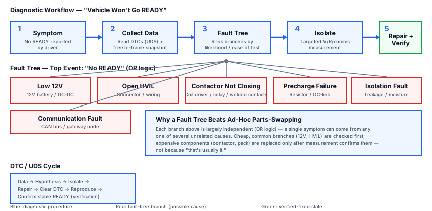
A fault tree starts from a single top event — here, “No READY” — and decomposes it downward into the conditions that could cause it, connected by AND/OR logic. An OR gate means any one branch alone is sufficient to cause the top event (which is the case for most of the branches below, since each represents an independent way the READY sequence can be interrupted). Framed this way, the technician’s job becomes “which branch is true right now,” which is answerable with a handful of targeted measurements rather than an open-ended search.
No READY
├── Low 12V → 12V battery / DC-DC
├── Open HVIL → connector / wiring
├── Contactor not closing → coil / relay
├── Precharge failure → resistor / DC-link
├── Isolation fault → leakage / moisture
└── Communication fault → CAN / gateway
FACT — A well-built fault tree also encodes prior probability: in practice, 12V and HVIL issues are disproportionately common compared to internal contactor failures, simply because low-voltage wiring and connectors are exposed to far more mechanical stress, moisture, and corrosion over the vehicle’s life. Good diagnostic procedures usually check the cheapest, most likely branches first.
4. Reading the Branches
Each branch in the tree points to a physically distinct failure mode, and recognizing the difference between them shortens the whole process considerably. A 12V fault shows up as intermittent or complete loss of low-voltage electronics — displays flickering, contactors not even attempting to close — because every HV control action is itself commanded by 12V-powered logic; the EV’s high-voltage system cannot bootstrap itself without a healthy low-voltage supply first. An open HVIL fault is almost always mechanical: a service connector not fully seated, a pinched or chafed interlock wire, or a connector housing damaged by heat or vibration; the system reacts by refusing to close contactors at all, since the interlock loop’s entire purpose is to guarantee no HV connector is open before energizing the bus.
A contactor fault can mean the coil driver never receives its command, the coil itself is open, or — more subtly — the contacts are welded shut or pitted so they no longer make clean contact; welded contacts are a special concern because the system may believe the contactor state is correct while the physical contact is actually damaged, which is why independent contact-state feedback exists in modern designs (see BMS Academy → BMS-06). A pre-charge failure usually means the pre-charge resistor has opened (often from repeated thermal cycling) or the DC-link capacitors will not accept charge in the expected time, which can point to a downstream short. An isolation fault is a leakage path between the HV bus and the chassis, most often introduced by moisture ingress at a connector or a chafed cable insulation; because this fault directly threatens the electric-shock protection barrier, it is treated as a high-priority safety fault rather than a mere inconvenience.
5. Diagnostic Methodology: From Symptom to Verified Repair
FACT — Faults are logged as Diagnostic Trouble Codes (DTCs) and read via the UDS protocol (ISO 14229) over the vehicle’s diagnostic interface (detail: BMS Academy → BMS-15).
A disciplined diagnostic sequence generally runs: (1) collect data — read all stored and pending DTCs, along with any available freeze-frame data (the sensor values captured at the moment the fault was set); (2) narrow the hypothesis space using the fault tree, ranking branches by likelihood and ease of testing; (3) isolate the root cause with targeted measurements (voltage, resistance, or communication checks at specific test points) rather than broad component replacement; (4) apply the corrective action; and (5) verify the fix by clearing the DTC, reproducing the original conditions, and confirming the vehicle now reaches READY and stays there. Skipping the verification step is a common source of comebacks, since an intermittent fault (for example, a marginal connector) can appear “fixed” simply because it was disturbed during inspection.
The diagram below shows this decision flow: an ambiguous symptom is decomposed by the fault tree into a small number of branches, each resolved by a specific class of measurement, converging on a verified repair.
6. FAQ
How are EV faults detected?
FACT — DTCs are read over OBD/UDS; for the HV system specifically, isolation resistance, individual cell voltages, and pack/component temperatures are continuously monitored, and any of them going out of range can itself set a fault.
What is the first step on a high-voltage fault?
FACT — Qualified personnel first de-energize the vehicle (commanding HV disable through the proper procedure) and verify isolation before any physical inspection of HV components.
Why not just replace the contactor whenever a vehicle won’t go READY?
INTERPRETATION — Contactors are one of many possible causes and are relatively expensive; replacing one without first confirming (via the fault tree and measurements) that it is actually the faulty branch risks unnecessary cost and leaves the real fault — often something simpler like a 12V or HVIL issue — unresolved.
7. Safety Warning
FACT — High-voltage systems carry a lethal electric-shock risk, and isolation faults in particular can indicate a compromised safety barrier. This lesson is theoretical and methodological only; physical inspection or intervention on a real vehicle’s HV system is performed exclusively by qualified personnel using proper PPE and OEM-approved procedures.
8. Summary
- The “no READY” scenario has many independent possible causes, from 12V and HVIL through contactor, pre-charge, isolation, and communication faults.
- A fault tree decomposes one ambiguous symptom into a small number of testable, largely independent branches (OR logic), which is far more efficient than ad-hoc parts-swapping.
- 12V and HVIL problems are common and cheap to check, so they are usually ruled out first.
- Contactor, pre-charge, and isolation faults each have distinct signatures (coil/contact issues, resistor/DC-link issues, and leakage/moisture respectively).
- The DTC/UDS workflow — collect data, narrow hypotheses, isolate root cause, repair, verify — turns a vague complaint into a confirmed fix.
9. Sources and Verification Note
The diagnostic protocol referenced here is ISO 14229 (UDS); no vehicle-specific thresholds or pinouts are used in this lesson.
- ISO 14229 — Unified Diagnostic Services.
- SAE J1715 — hybrid and electric vehicle terminology.
- ISO 26262 — general fault classification concepts referenced conceptually (detail: EV-34).
ASSUMPTION — Source versions/titles may change; every source must be re-verified before publication.
Next Lesson
- EV-34 — Functional Safety (ISO 26262): HARA, ASIL, and safety goals.
Technical Diagrams
Quiz
What is one possible cause of 'vehicle won't go READY'?
Low 12V is one cause of failing to reach READY.
What does a fault tree do?
A fault tree systematically narrows possible causes.
What does an open HVIL fault indicate?
An open HVIL indicates an HV connector/wiring opening.
What is precharge failure related to?
Precharge pre-charges the DC-link capacitor; failure blocks READY.
What does an isolation fault indicate?
An isolation fault indicates leakage/moisture between HV bus and chassis.
How are diagnostic faults recorded?
Faults are recorded as DTCs and read via UDS.