
- Distinguish between cell, module, and pack in an EV battery.
- Summarize the differences between core cell chemistries such as NMC and LFP.
- Tell apart voltage, capacity (Ah), energy (Wh/kWh), power (W), current, and C-rate.
- Calculate how series/parallel connection affects voltage, capacity, and energy.
- Identify the core failure modes threatening a battery (overvoltage, overcurrent, overtemperature, imbalance, isolation fault, thermal runaway).
- Explain why a BMS is a mandatory safety and control layer, not an optional extra.
BMS-01 — EV Battery Fundamentals and Why a BMS Is Non-Negotiable
ASSUMPTION — This is the first lesson in Autovoltix EV Battery Academy’s Battery Management System (BMS) track, and it introduces the foundational concepts every later lesson builds on. The “96s2p, 400 V class, 80 kWh” battery used throughout the course is a hypothetical example for teaching purposes only — it does not describe any real OEM pack.
1. What Is an EV Battery?
The high-voltage battery in an electric vehicle is the primary energy source feeding the drive motor. Compared with a fuel tank in a combustion car, an EV battery does more than just store energy — it’s a system that’s actively monitored, protected, and controlled.
FACT — Energy storage is a core component of battery electric vehicles (BEVs), plug-in hybrids (PHEVs), and hybrids (HEVs). The vast majority of today’s EVs use lithium-ion (Li-ion) batteries, because Li-ion offers a higher energy-to-mass and energy-to-volume ratio, a high power-to-weight ratio, high efficiency, decent high-temperature performance, long life, and low self-discharge compared with other storage technologies. (Source: U.S. Department of Energy, Alternative Fuels Data Center)
It helps to think of the battery system as three nested levels.
1.1 Cell
A battery cell is the smallest independent unit that converts electrochemical energy directly into electrical energy. A Li-ion cell is built from:
- Anode — the electrode that gives up electrons during discharge (typically graphite-based)
- Cathode — the electrode that accepts electrons during discharge (materials such as NMC, NCA, LFP)
- Separator — a thin membrane that electrically isolates anode from cathode while letting ions pass through
- Electrolyte — the conductive medium that carries lithium ions between electrodes
FACT — How a Li-ion cell works: during charging, lithium ions move from cathode to anode through the electrolyte; during discharge, they move the other way. Electrons flow through the external circuit, and that flow does the work.
1.2 Module
A battery module is the intermediate structure where a set number of cells are connected in series and/or parallel and mechanically grouped together. Modules make manufacturing, thermal management, and servicing easier.
1.3 Pack
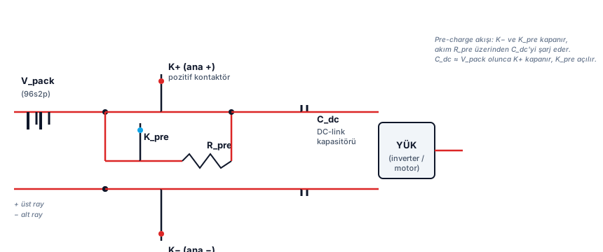
A battery pack is the complete assembly — modules (or cells directly) plus the BMS, thermal management system, contactors, fuses, and high-voltage (HV) connections — that forms the vehicle’s final energy store.
EXAMPLE — Architectural approaches vary by manufacturer. The classic Cell-to-Module (CTM) approach builds cells into modules and modules into a pack. The newer Cell-to-Pack (CTP) approach skips the module step and integrates cells directly into the pack. Cell-to-Chassis goes further and makes the cells a structural part of the vehicle body itself. We’ll compare these approaches in more detail later in the course.
2. Cell Chemistry
“Li-ion” is a family name; it splits into different chemistries depending on the cathode material. The two most common families in the EV industry are NMC and LFP.
FACT — Cell chemistry directly determines nominal voltage, energy density, power capability, cost, lifespan, and safety behavior. That’s why BMS design adapts its limits and algorithms to the specific chemistry it’s managing.
2.1 NMC (Nickel-Manganese-Cobalt)
NMC is a Li-ion chemistry that uses a combination of nickel, manganese, and cobalt in the cathode.
FACT — NMC cells typically have a nominal voltage around 3.6–3.7 V, and their energy density is generally higher than LFP’s. That’s why NMC is common in passenger vehicles chasing long range.
ASSUMPTION — This course uses 3.7 V as the NMC nominal cell voltage. That’s a representative figure; the actual value depends on the manufacturer’s specification.
2.2 LFP (Lithium Iron Phosphate)
LFP is a Li-ion chemistry that uses iron phosphate in the cathode.
FACT — LFP cells typically have a nominal voltage around 3.2–3.3 V, lower than NMC’s. In exchange, LFP generally offers longer cycle life, lower cost, and better thermal stability — but usually at lower energy density than NMC.
EXAMPLE — Building the same 400 V-class pack with LFP requires more cells in series than with NMC, because each LFP cell produces less voltage. This shows why the relationship between cell count and pack voltage matters in practice.
2.3 Why Chemistry Is the BMS’s Business
FACT — The BMS has to know the charge/discharge voltage limits, temperature window, and SOC-voltage (OCV) relationship that come with each chemistry. An NMC cell and an LFP cell have different “fully charged” and “fully discharged” voltages, and the BMS triggers protection whenever either limit is crossed.
2.4 Next-Generation Cell Chemistries (A Look Ahead)
NMC and LFP dominate today’s market, but a few contenders are waiting in the wings. The table below summarizes them; the 96s2p/400V/80kWh example used throughout the course still assumes NMC.
| Chemistry | Status | Strength | Weakness | What changes for the BMS |
|---|---|---|---|---|
| Sodium-ion (Na-ion) | Limited series production has started (CATL, ~2023) | Cheap, abundant raw material | Lower energy density | OCV-SOC curve and voltage window differ from Li-ion; calibration (BMS-08) and protection limits (BMS-13) have to be derived from scratch |
| Lithium-sulfur (Li-S) | R&D / early stage | Very high theoretical energy density | Cycle life and stability have historically been the weak point | Discharge voltage profile is low and flat — OCV-based SOC estimation (BMS-08) needs to be designed from the ground up |
| Solid-state | Pilot production / roadmap stage (Toyota, QuantumScape, Samsung SDI) | Higher energy density, possibly faster charging, different thermal behavior | Commercialization timelines have slipped for years | The thermal-runaway model built around liquid-electrolyte leakage (Section 7.10) no longer applies as-is; new failure modes add new parameters to the SOH model (BMS-09) |
| Semi-solid-state | Limited field deployment (e.g. NIO, 2023) | Commercializing earlier than full solid-state | Not one standard chemistry — varies by manufacturer | Internal resistance/thermal behavior may resemble classic Li-ion, but cell-specific calibration (BMS-20) is still required |
ASSUMPTION — This table summarizes general trends based on public announcements and the broader literature; it is not a specific cell’s confirmed performance figure or safety certification. Read the solid-state timeline especially cautiously — the industry has repeatedly pushed it back for years.
The common thread: whatever the chemistry, the BMS’s core job doesn’t change — it just needs to be recalibrated with that chemistry’s voltage window, OCV curve, and failure modes.
3. Cell Formats
Li-ion cells are manufactured in three main physical formats:
- Cylindrical — a wound electrode structure inside a metal can (e.g., format names like 18650, 2170, 4680)
- Prismatic — a layered/wound structure inside a rigid rectangular metal or hard case
- Pouch — a layered structure inside a flexible, laminated foil case
FACT — Format choice is a trade-off between packaging density, thermal management, mechanical strength, cost, and energy density. There’s no single “best” format — the choice depends on vehicle and pack requirements.
EXAMPLE — Cylindrical cells offer high mechanical strength and good thermal management potential, but relatively low packaging efficiency (more wasted space). Pouch cells offer high packaging efficiency and energy density but need mechanical support and swelling management. Prismatic cells sit somewhere in between.
ASSUMPTION — In our hypothetical example (Section 6) we’ll assume a large-format prismatic cell, representative of high-capacity single cells (112.5 Ah).
4. Core Electrical Quantities
This section defines the quantities the BMS continuously measures and manages.
4.1 Voltage
Voltage is the electrical potential difference between two points, measured in Volts (V).
FACT — A cell’s voltage changes with SOC, temperature, and load (current). The BMS distinguishes two different voltage concepts: nominal voltage (a chemistry-specific reference value) and instantaneous terminal voltage (the measured value at any moment).
FACT — In series, voltages add up. If n identical cells are connected in series, total voltage is n × V_cell. In parallel, voltage stays the same, and capacity adds up.
4.2 Capacity and Amp-hours (Ah)
Capacity is the amount of electric charge a cell can store under given conditions, measured in Amp-hours (Ah).
FACT — 1 Ah is the charge delivered by 1 Amp of current over 1 hour. In other words, Capacity (Ah) = Current (A) × Time (h).
EXAMPLE — A 100 Ah battery can theoretically be discharged at 100 A for 1 hour, or at 10 A for 10 hours (ideally, ignoring internal resistance and the Peukert effect).
FACT — In parallel, capacities add up. If p identical cells are connected in parallel, total capacity is p × C_cell.
4.3 Energy — Wh and kWh
Energy is the total amount of work a battery can deliver, measured in Watt-hours (Wh) or kilowatt-hours (kWh).
Formula:
E (Wh) = V (V) × Ah (Ah)- E: Energy (Wh)
- V: Voltage (V)
- Ah: Capacity (Amp-hours)
EXAMPLE — A cell at 3.7 V and 100 Ah stores: E = 3.7 V × 100 Ah = 370 Wh = 0.37 kWh.
FACT — 1 kWh = 1000 Wh. An EV pack’s energy is usually expressed in kWh (e.g., “an 80 kWh battery”).
4.4 Power — Watts
Power is energy transferred per unit time, measured in Watts (W).
Formula:
P (W) = V (V) × I (A)- P: Power (W)
- V: Voltage (V)
- I: Current (A)
FACT — Power tells you “how fast” energy is transferred; energy tells you “how much in total.” Energy = Power × Time (Wh = W × h).
4.5 Current
Current is the amount of electric charge passing per unit time, measured in Amps (A). The BMS measures current with a sign convention — charge (into the cell, typically positive) and discharge (out of the cell).
4.6 C-rate
C-rate normalizes current against a battery’s nominal capacity.
Formula:
C-rate = I (A) / C_nominal (Ah)- C-rate: normalized current (dimensionless, read as “C”)
- I: instantaneous current (A)
- C_nominal: nominal capacity (Ah)
FACT — 1C is the current that fully discharges (or fully charges) a battery’s nominal capacity in exactly 1 hour. 0.5C is half that current; 2C is double.
EXAMPLE — For a cell with 112.5 Ah nominal capacity: 1C = 112.5 A, 0.5C ≈ 56.3 A, 2C = 225 A.
FACT — Why does C-rate matter? Because cells experience more internal loss (heating) and greater voltage sag at higher C-rates. The BMS continuously monitors current to stay within safe C-rate limits.
5. Internal Resistance, OCV, SOC, Temperature, and Aging
These are the BMS’s “invisible” but critical concepts.
5.1 Internal Resistance
Internal resistance is the total resistance from ionic and electronic conduction inside a cell, measured in Ohms (Ω) or, more practically, milliohms (mΩ).
FACT — When current flows, it produces a voltage drop across internal resistance: V_drop = I × R_internal. That’s why terminal voltage under load falls below OCV during discharge (and rises above it during charge).
FACT — Power dissipated across internal resistance turns into heat: P_loss = I² × R_internal. This heating becomes significant at high currents, which is why the BMS manages current and temperature together.
FACT — Internal resistance grows with aging (especially SEI growth and electrolyte breakdown), contributing to reduced power capability. This is one of the core inputs to SOH (State of Health) estimation.
5.2 Open Circuit Voltage (OCV)
OCV is the terminal voltage of a cell when no current is being drawn and the cell is in electrochemical equilibrium.
FACT — OCV has a strong, repeatable relationship with SOC. This “OCV–SOC curve” is one of the core maps the BMS uses for SOC estimation.
FACT — OCV and terminal voltage are not the same thing. Under load, terminal voltage deviates from OCV due to internal resistance and polarization effects. That’s why SOC can’t be reliably calculated by “just reading the terminal voltage” (more in BMS-08).
5.3 State of Charge (SOC)
SOC is the ratio of a battery’s currently available capacity to its full capacity, usually expressed as a percentage.
SOC (%) = (Remaining capacity / Full capacity) × 100FACT — SOC underlies the “range/percentage” figure shown to the driver and drives energy-management decisions. A wrong SOC estimate can lead to wrong derating, wrong range estimates, and insufficient protection.
5.4 Temperature
FACT — Temperature directly affects cell chemistry, and therefore performance, safety, and lifespan. At low temperature, internal resistance rises and power capability falls; at high temperature, degradation accelerates and thermal runaway risk increases.
FACT — The BMS evaluates cells not just as a “single temperature value” but as a temperature distribution (gradient) across the pack. One overheating region can be a real risk even while the average looks normal.
5.5 Aging
FACT — Li-ion cells degrade over time and with use. Aging splits into two main components: cycle aging — caused by charge/discharge cycles — and calendar aging — which progresses with time and temperature, independent of use.
FACT — Aging shows up as capacity fade and power fade. The BMS tracks this degradation through SOH estimation and updates usable power/energy limits accordingly (more in BMS-09).
6. A Hypothetical Battery Example — Worked Calculations
To keep the course consistent, we’ll use a single hypothetical pack throughout. It does not describe a real OEM product.
ASSUMPTION — Hypothetical pack: 96s2p, 400 V class, roughly 80 kWh. Cell: NMC, nominal 3.7 V, 112.5 Ah (large-format prismatic).
6.1 Notation: what does “96s2p” mean?
- 96s → 96 cells connected in series
- 2p → 2 cells connected in parallel at each series stage
FACT — Total cell count = series × parallel = 96 × 2 = 192 cells.
6.2 Pack Voltage
Formula:
V_pack = N_series × V_cell- V_pack: pack nominal voltage (V)
- N_series: number of series cells (96)
- V_cell: cell nominal voltage (3.7 V)
Calculation:
V_pack = 96 × 3.7 V = 355.2 V (nominal)EXAMPLE — “400 V class” describes the operating range, not the nominal value. If a typical NMC cell charges up to 4.2 V and discharges down to ~2.8 V:
- Maximum pack voltage ≈ 96 × 4.2 V = 403.2 V
- Minimum pack voltage ≈ 96 × 2.8 V = 268.8 V
6.3 Pack Capacity
Formula:
C_pack = N_parallel × C_cell- C_pack: pack capacity (Ah)
- N_parallel: number of parallel cells (2)
- C_cell: cell capacity (112.5 Ah)
Calculation:
C_pack = 2 × 112.5 Ah = 225 Ah6.4 Pack Energy
Formula:
E_pack = V_pack × C_packCalculation:
E_pack = 355.2 V × 225 Ah = 79,920 Wh ≈ 79.9 kWhEXAMPLE — The result rounds to roughly 80 kWh, which is why we call this the “80 kWh class” pack (79.9 kWh rounds to 80 kWh).
6.5 Current and C-rate
EXAMPLE — Since the pack is 225 Ah: 1C = 225 A, 0.5C ≈ 112.5 A, 2C = 450 A. During acceleration the pack may briefly deliver several C’s worth of current; during DC fast charging, high current flows into the pack. The BMS tracks both the magnitude and duration of these currents.
6.6 Power
Formula:
P_pack = V_pack × IEXAMPLE — Drawing 225 A (1C) at a nominal 355.2 V gives: P = 355.2 V × 225 A = 79,920 W ≈ 80 kW. In other words, “at ~1C the pack delivers ~80 kW” (illustrative — real peak power may be higher).
7. Problems That Threaten a Battery
This section covers the core failure modes that are the entire reason a BMS exists. For each one we briefly cover “what happens?” and “what does the BMS do?” — details come in later lessons.
7.1 Overvoltage
FACT — If a cell is pushed above the manufacturer’s maximum charge voltage (overcharge), the electrolyte can break down, excessive heating can occur, and lithium plating can form on the anode. Lithium plating causes both capacity loss and internal short-circuit risk.
FACT — BMS response: cut or reduce charge current, open the charge contactor, and log the fault. Cell-level measurement is critical here, because the total pack voltage can look perfectly normal while a single cell is overcharged.
7.2 Undervoltage
FACT — If a cell drops below its minimum discharge voltage (over-discharge), irreversible chemical changes can occur at the electrodes, causing permanent capacity loss. Charging a cell after over-discharge can also carry a safety risk.
FACT — BMS response: limit or cut discharge, disconnect the load, and log the fault.
7.3 Overcurrent
FACT — Exceeding the defined safe current limit causes excessive heating (I²R losses) and excessive stress on electrodes and conductors.
FACT — BMS response: continuously measure current; limit the power request (derating) past certain thresholds, and open the HV contactors at higher thresholds.
7.4 Short Circuit
FACT — A short circuit creates a sudden, uncontrolled high current through an extremely low-resistance path. This current reaches very high levels within milliseconds, carrying serious heating/arcing risk.
FACT — A short circuit happens too fast for a software-only BMS response to be sufficient. That’s why hardware protection elements like fuses and, where needed, pyro fuses step in. The BMS works alongside these elements (more in BMS-06/BMS-07).
7.5 Overtemperature
FACT — High temperature accelerates chemical breakdown and raises thermal runaway risk. Overtemperature can result from high current, poor cooling, or an external heat source.
FACT — BMS response: limit power (derating), request more cooling from the thermal management system, and disconnect energy at a critical threshold.
7.6 Undertemperature
FACT — At low temperature, electrolyte conductivity drops, internal resistance rises, and power capability falls. More importantly, charging at low temperature significantly increases lithium plating risk.
FACT — BMS response: severely limit or block charge power at low temperature, and request heating if needed.
7.7 Cell Imbalance
FACT — Series-connected cells can end up with different SOC/voltage values due to manufacturing tolerances, temperature differences, and uneven aging. Imbalance reduces the pack’s usable capacity and pushes individual cells to their limits sooner.
FACT — The BMS measures the differences between cells and reduces them through cell balancing (more in BMS-11).
7.8 Degradation
FACT — Degradation isn’t a “sudden failure” — it’s a gradual loss of capacity and power over time. The BMS tracks this through SOH estimation, adjusts usable energy/power limits accordingly, and reports it to the driver or service technician.
7.9 Isolation Fault
FACT — If the isolation resistance between the HV circuit and the vehicle chassis (ground) drops below a safe threshold, it creates an electric shock risk. The BMS continuously monitors isolation resistance and disconnects HV if it detects a fault (more in BMS-13).
7.10 Thermal Runaway
FACT — Thermal runaway is a self-sustaining, uncontrollable temperature rise that occurs when exothermic (heat-releasing) reactions inside a cell pass the point where heat generation exceeds heat dissipation. It can be triggered by overcharge, internal short circuit, mechanical damage, or external heating.
FACT — The BMS’s role in thermal runaway is limited: it provides preventive limits (overvoltage/overtemperature protection), early detection (rapid temperature/voltage anomalies), and reaction (disconnecting HV, requesting cooling, alerting). But it cannot stop thermal runaway on its own — it works alongside physical safety layers (venting, thermal barriers, mechanical protection).
FACT — This is why “the BMS guarantees total battery safety” is a misleading claim. Safety is a multi-layered approach built jointly from cell design, mechanical structure, thermal management, electrical protection, and the BMS.
8. Why Is a BMS Required?
Summarizing the problems above, a Li-ion battery cannot simply be treated as a passive “energy tank”, because:
- Narrow safe operating window — cells only operate safely within specific voltage, current, and temperature ranges.
- Cell-level protection, not just averages — the pack average can look normal while a single cell goes out of bounds.
- Hidden states — SOC, SOH, and internal resistance can’t be measured directly; they must be estimated with algorithms.
- Fast events — things like short circuits require hardware-level protection.
- Long-term durability — without balancing and thermal management, a pack degrades prematurely.
FACT — A Battery Management System (BMS) is the electronic system that monitors, protects, and controls cells and the pack to keep it safe, efficient, and long-lasting. Without a BMS, a high-voltage Li-ion pack cannot be safely used in a production vehicle.
9. What Does a BMS Actually Do? (Overview)
The BMS’s core functions are (each will get its own lesson later):
- Measurement — cell voltages, cell/pack temperatures, pack current, and isolation resistance.
- State Estimation — SOC (State of Charge), SOH (State of Health), and SOP (State of Power).
- Protection — reacting to voltage/current/temperature limit violations (derating, opening contactors).
- Balancing — reducing SOC/voltage differences between cells.
- Thermal Management — generating cooling/heating requests.
- Communication — exchanging data with the vehicle control unit (VCU) and other systems (CAN, etc.).
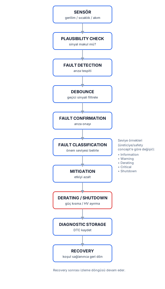
- Fault Management & Diagnostics — detecting, classifying, logging, and reporting faults.
- Safety — HV safety, isolation monitoring, and functional safety mechanisms.
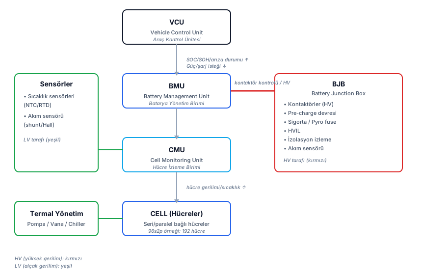
FACT — BMS architecture generally follows this hierarchy: Cell → Cell Monitoring Unit (CMU) → Battery Management Unit (BMU) → Vehicle Control Unit (VCU). We’ll cover this architecture in detail in BMS-02.
10. Safety Notice (IMPORTANT)
FACT — High-voltage (HV) battery systems can cause fatal electric shock and fire risk. This course content is intended purely for theoretical, engineering, design, simulation, and test-methodology purposes.
FACT — Opening a real HV pack, working on an energized system, creating a short circuit, or running cell abuse/thermal-runaway experiments must only be done in a professional laboratory setting, with proper personal protective equipment (PPE), isolation, procedures, and qualified personnel. This course is not amateur how-to instruction.
11. Summary
- Cell → Module → Pack: a battery is built hierarchically, starting from the smallest unit (cell) up through module and pack.
- Chemistry and format: NMC tends toward higher voltage/energy density, LFP toward longer life/lower cost. Cylindrical, prismatic, and pouch formats each trade off differently.
- Core quantities: voltage (V), capacity (Ah), energy (Wh/kWh), power (W), current (A), and C-rate are all linked by formulas.
- Series/parallel: series connection raises voltage, parallel connection raises capacity.
- Hidden states: internal resistance, OCV, SOC, temperature, and aging can’t be measured directly — they’re managed with algorithms.
- Failure modes: overvoltage, undervoltage, overcurrent, short circuit, over/undertemperature, imbalance, degradation, isolation fault, and thermal runaway are the entire reason a BMS exists.
- The BMS’s role: it provides monitoring, estimation, protection, balancing, thermal management, communication, and fault management — but battery safety is the result of a multi-layered system.
12. Sources and Verification Note
The technical claims in this lesson rest on the source categories below. No proprietary OEM architecture, CAN ID, or confidential design information has been used. Baseline values like voltage/capacity/C-rate are established textbook-level engineering knowledge; cell-specific figures are explicitly flagged as ASSUMPTION.
- U.S. Department of Energy (DOE), Alternative Fuels Data Center — “Batteries for Electric Vehicles” (Li-ion battery properties and EV use).
- Gregory L. Plett, Battery Management Systems, Volume I: Battery Modeling and Volume II: Equivalent-Circuit Methods (cell modeling, OCV, SOC, internal resistance).
- ISO 26262 — Road vehicles functional safety standard (safety concepts; details in BMS-17).
- UNECE R100 — Electric vehicle safety regulation (HV safety and battery safety requirements; general reference).
ASSUMPTION — Source titles/versions may change over time; this lesson reflects information verified as of its publication date.
Next Lesson
- BMS-02 — BMS Architecture: the Cell → CMU → BMU → VCU hierarchy, centralized/distributed/modular architectures, and how the components relate.
Technical Diagrams


Interactive Calculator
Battery Pack Calculator
Hücre parametrelerini girerek paket değerlerini hesaplayın. Varsayılanlar dersin hipotetik örneğidir (96s2p).
Quiz
What happens to pack voltage when 96 cells are connected in series?
In a series connection, voltages add up. If each cell is ~3.7 V nominal, a 96s pack is roughly 355 V nominal.
What's the difference between a cell's capacity (Ah) and its energy (Wh)?
E = V × Ah. Ah expresses electric charge (current × time), Wh expresses energy; voltage is the multiplier that connects them.
What does C-rate express?
C-rate is current divided by nominal capacity. 1C corresponds to 100 A for a 100 Ah battery.
Which statement is generally true when comparing NMC and LFP cell chemistry?
NMC cells are typically ~3.6–3.7 V nominal, LFP cells ~3.2–3.3 V. NMC generally offers higher energy density.
Why does a gap exist between a cell's terminal voltage and its OCV (open circuit voltage)?
When current flows, an IR drop across internal resistance and electrochemical polarization both occur, making terminal voltage diverge from OCV.
How do voltage and capacity behave in a parallel cell group (e.g., 2p)?
In a parallel connection, voltage stays constant while total capacity becomes the sum of the individual cells' capacities (and current is shared).
Why is it necessary to monitor individual cell voltages (beyond total pack voltage) in a series pack?
Total voltage shows an average; an imbalanced or faulty cell can exceed its individual limits while the pack average still looks normal.
What's the most accurate description of the BMS's role in thermal runaway?
The BMS provides preventive limits, monitoring, and reaction for thermal runaway, but it doesn't guarantee total battery safety on its own — it works alongside mechanical, electrical, and thermal protection layers.
For a 96s2p pack with cells at 3.7 V nominal and 112.5 Ah capacity, what's the approximate total energy (kWh)?
Pack voltage ≈ 96 × 3.7 ≈ 355 V; pack capacity ≈ 2 × 112.5 = 225 Ah; energy ≈ 355 V × 225 Ah ≈ 80 kWh.
Which of these faults can the BMS manage directly with derating, while an event like a short circuit has to be handled differently?
Slowly developing overload/overtemperature can be bounded with software-based derating; a short circuit is too fast, and passive/hardware protection layers like a fuse step in.
Glossary
| English Term | Definition |
|---|---|
| Battery Cell | The smallest independent energy storage unit that converts electrochemical energy directly into electrical energy. |
| Battery Module | The intermediate structure where a set number of cells are connected in series/parallel and mechanically and electrically grouped together. |
| Battery Pack | The complete assembly of modules and/or cells together with the BMS, thermal management, and high-voltage components that forms the vehicle's final energy store. |
| Battery Management System (BMS) | The electronic system that monitors, protects, and controls cell/pack state to keep the battery pack safe, efficient, and long-lasting. |
| Nominal Voltage | A reference voltage, defined by a cell's chemistry, that represents the characteristic midpoint of the discharge curve. |
| Capacity | The amount of electric charge a cell can store/deliver under given conditions; expressed in Amp-hours (Ah). |
| Energy | The total work-delivering capacity a battery stores; expressed in Watt-hours (Wh) or kilowatt-hours (kWh). |
| Power | Energy transferred per unit time; expressed in Watts (W). Electrically, P = V × I. |
| C-rate | Current normalized against a battery's nominal capacity; 1C is the current that fully discharges the capacity in one hour. |
| Internal Resistance | The total resistance from ionic/electronic conduction inside a cell; causes a voltage drop and heating under load. |
| Open Circuit Voltage (OCV) | A cell's terminal voltage when no current is drawn (at equilibrium); shows a strong correlation with SOC. |
| State of Charge (SOC) | The ratio of a battery's currently available capacity to its full capacity; expressed as a percentage (%). |
| State of Health (SOH) | A degradation indicator expressing a battery's remaining capacity and power capability relative to when it was new. |
| Series Connection | Connecting one cell's (+) terminal to the next cell's (−) terminal; increases total voltage, capacity stays the same. |
| Parallel Connection | Joining cells' matching terminals together; increases total capacity, voltage stays the same. |
| Overvoltage | A cell or pack voltage exceeding its safe upper limit; creates lithium plating and degradation risk. |
| Undervoltage | A cell or pack voltage dropping below its safe lower limit; creates permanent capacity loss risk. |
| Overcurrent | Exceeding the defined safe current limit; creates excessive heating and damage risk. |
| Thermal Runaway | A chain reaction in which exothermic reactions inside a cell become self-sustaining, turning into an uncontrollable temperature rise. |
| Isolation Fault | The isolation resistance between the high-voltage circuit and the vehicle chassis dropping below a safe threshold. |
| Cell-to-Pack (CTP) | A design approach that integrates cells directly into the pack structure, skipping the module step. |
| NMC (Nickel-Manganese-Cobalt) | A Li-ion cell chemistry family using a nickel/manganese/cobalt combination in the cathode; tends toward high energy density. |
| LFP (Lithium Iron Phosphate) | A Li-ion cell chemistry family using iron phosphate in the cathode; generally offers longer cycle life and better thermal stability. |
| Sodium-ion Battery (Na-ion) | A Li-ion alternative cell chemistry using sodium instead of lithium; cheaper, more abundant raw material but typically lower energy density. |
| Lithium-Sulfur Battery (Li-S) | A cell chemistry offering high theoretical energy density potential, not yet in widespread automotive series production due to cycle-life/stability limitations. |
| Solid-State Battery | A next-generation cell technology using a solid electrolyte instead of liquid; potentially higher energy density and different thermal safety behavior. |
| Semi-Solid-State Battery | An intermediate technology family using a gel/semi-solid electrolyte between liquid and full solid-state; commercializing earlier than full solid-state. |