
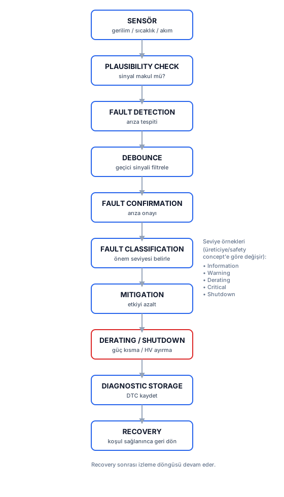
- Explain the fault management flow (detection → confirmation → classification → reaction → recovery).
- Identify fault severity levels (Information, Warning, Derating, Critical, Shutdown).
- Explain debounce and plausibility.
- Work through typical BMS fault scenarios via a symptom → diagnosis → reaction chain.
BMS-13 — Fault Management
1. Noise or Fault?
A BMS processes thousands of measurement samples at any given moment. Some reflect a real fault, some are transient noise, and some are the sensor’s own malfunction. Fault management’s entire job is to tell these three apart and respond to each proportionately:
Sensor → Plausibility Check → Fault Detection → Debounce → Fault Confirmation
→ Fault Classification → Mitigation → Derating/Shutdown → Diagnostic Storage → Recovery
This flow keeps a transient signal from mistakenly turning into a fault.
2. Plausibility and Debounce
Plausibility checks whether a signal is physically possible — a temperature sensor reading -40 °C is probably open-circuit, for instance. This check happens three ways: an absolute range check (a cell voltage outside 0-5 V is invalid), a rate-of-change check (a 500 mV jump between samples is physically impossible), and cross-validation (comparing against neighboring cells or current-voltage consistency).
Debounce confirms a signal for a set duration to tell a real fault apart from momentary noise. When a cell voltage crosses a threshold, the BMS doesn’t immediately call it a fault — it checks whether the threshold breach persists over, say, 100 ms (several measurement cycles). If the value returns to normal by the 3rd cycle, it was probably measurement noise, and the fault isn’t confirmed.
3. Classification and Reaction
A fault that survives debounce gets confirmed and classified by severity. Typical levels: Information, Warning, Derating, Critical, Shutdown (these can vary by manufacturer and safety concept). A minor sensor deviation might be a “Warning,” while cell overvoltage might require “Shutdown” (opening the contactors).
The reaction is proportionate: Derating gradually reduces power, Shutdown opens the HV contactors and disconnects energy. A fault is logged as a DTC (Diagnostic Trouble Code) and kept for service. Recovery is a safe return to normal once the fault condition clears — some faults recover automatically, others need service intervention.
4. Case Studies
The six scenarios below walk through typical field-encountered BMS faults using a Symptom → Possible Causes → Detection → Diagnosis → Mitigation → Recovery framework.
ASSUMPTION — These case studies are conceptual, educational examples; they are not a real vehicle’s official diagnostic/service procedure and don’t contain OEM-specific concrete thresholds or procedures.
Case 1 — One Cell Reads 80 mV Higher Than the Rest
- Symptom: One cell’s voltage sits ~80 mV above the average of the rest of the series string.
- Possible causes: a real SOC imbalance (manufacturing tolerance/different aging), a gain/offset error in the measurement channel, extra resistance in the sense wire.
- Detection: flagged when the inter-cell difference exceeds the balancing threshold (BMS-11).
- Diagnosis: if the gap persists at rest (no current, OCV valid), a real SOC difference is likely; if it only shows up under load and vanishes at rest, a measurement error becomes more likely.
- Mitigation: if it’s a real difference, balancing kicks in; if a measurement error is suspected, the channel is flagged “low confidence” and cross-checked against neighboring data.
- Recovery: once balancing brings the gap below threshold, things return to normal; a measurement error may require service/calibration.
Case 2 — Pre-charge Doesn’t Finish in the Expected Time
- Symptom: in the PRECHARGE state, DC-link voltage doesn’t reach the target within the expected ~5τ.
- Possible causes: the pre-charge resistor is open or its value has increased, the contactor hasn’t fully closed, an unexpected leak on the DC-link, or the capacitance is larger than expected.
- Detection: the BMS tracks pre-charge duration and DC-link voltage against a defined timeout threshold.
- Diagnosis: if voltage never rises, suspicion falls on the contactor/resistor; if it rises slowly, suspicion falls on an increased resistance value or an unexpected load.
- Mitigation: the BMS aborts pre-charge on timeout, keeps the contactors open, and doesn’t allow HV activation.
- Recovery: only retried after the root cause is fixed; automatic recovery isn’t recommended.
Case 3 — A Temperature Sensor Reads -40 °C
- Symptom: one channel reads -40 °C, inconsistent with neighboring sensors and ambient conditions.
- Possible cause: an open circuit on the NTC sense line — the voltage-divider output locks to the edge of the range when open.
- Detection: a plausibility check catches a deviation that’s physically implausible compared with neighboring sensors.
- Diagnosis: a sensor/channel fault (not a cell fault).
- Mitigation: the channel is flagged invalid; the neighboring sensors’ data or the last valid reading is used temporarily, and derating decisions are made more conservatively.
- Recovery: the channel is reactivated after service repair and an EOL-like verification.
Case 4 — A Current Sensor Shows a +20 A Offset
- Symptom: while the vehicle is parked (real current ≈ 0), the sensor keeps reading +20 A.
- Possible causes: calibration drift, temperature-driven drift, a sensor hardware fault.
- Detection: the BMS compares the reading against zero while the vehicle is asleep/resting (a known zero-current condition).
- Diagnosis: an offset that’s constant and doesn’t change over time points to calibration drift; one that changes with temperature points to thermal drift.
- Mitigation: its effect on Coulomb counting is bounded by periodic OCV correction; if the offset is large, SOC confidence is lowered and a more conservative SOP is applied.
- Recovery: fixed via a calibration update or sensor replacement.
Case 5 — One Cell’s Voltage Suddenly Drops
- Symptom: one cell’s voltage drops noticeably faster than the others over a short period.
- Possible causes: rising internal resistance/a partial fault, a possible internal short-circuit tendency (a serious safety risk), a measurement channel fault.
- Detection: the BMS tracks voltage rate-of-change (dV/dt) and consistency against neighboring cells; an abnormally fast drop can be classified as “critical.”
- Diagnosis: if accompanied by a temperature rise, suspicion of an internal short circuit strengthens; if temperature is stable, a measurement channel fault is also possible.
- Mitigation: safety comes first — the BMS treats the suspect cell as worst-case and limits the load or disconnects HV.
- Recovery: generally not suited to automatic recovery; needs service/investigation.
Case 6 — CAN Communication Drops
- Symptom: the BMS’s CAN communication with the VCU or a CMU doesn’t respond within the expected time.
- Possible causes: a cable/connector fault, a transceiver fault, EMI, or a fault in the other node itself.
- Detection: the BMS tracks whether expected periodic messages arrive within a timeout window (message timeout).
- Diagnosis: if data is lost from only one CMU, a daisy-chain break is the leading suspect; if all communication with the VCU is lost, a CAN line/transceiver fault is the leading suspect.
- Mitigation: functions depending on the lost data default to the safe side; if VCU communication is fully lost, the vehicle typically enters a safe mode (limp-home).
- Recovery: once communication and data consistency are restored, things return to normal; repeated dropouts warrant a service investigation.
5. How It’s Verified in Production
HIL testing systematically injects scenarios like the ones above, confirming correct detection time, correct classification, and correct reaction for each fault (BMS-19).
6. How It Connects to Other Systems
Fault management takes data from every measurement chain (BMS-03, BMS-04, BMS-05), can push the state machine (BMS-14) into the FAULT state, is the runtime realization of the functional safety concept (BMS-17), and exposes diagnostic records to service tools over CAN/UDS (BMS-15).
Summary
- Plausibility and debounce prevent false faults; classification determines a proportionate reaction.
- Derating/shutdown deliver safety; DTC logging supports service.
- The case studies show how the symptom-diagnosis-reaction chain plays out in the field.
Sources
- ISO 26262 — fault detection and reaction.
- Gregory L. Plett, Battery Management Systems, Volume II — diagnostics.
Technical Diagrams
Quiz
What does debounce do?
Debounce confirms a signal over a set duration, separating noise from a real fault.
What does a plausibility check verify?
Plausibility checks whether a measured value is physically reasonable (range, rate of change, cross-validation).
If a cell voltage reads 80 mV high and the gap persists at rest, what's the most likely cause?
If the gap persists at rest (while OCV is valid), a real SOC/OCV difference becomes more likely.
What's the BMS's correct response to a pre-charge timeout?
On timeout, the system stays on the safe side; HV activation isn't allowed.
Why can an abnormally fast drop in a cell voltage's dV/dt be classified as 'critical'?
An abnormally fast voltage drop can signal rising internal resistance or a possible internal short-circuit tendency; safety comes first.
What's the BMS's typical response when CAN communication from a CMU is lost?
On data loss, the system stays on the safe side; the affected data is treated as unreliable and derating is applied if needed.
What's a DTC's (Diagnostic Trouble Code) role?
A DTC is a standard record identifying a fault, readable via UDS, supporting the service process.
Glossary
| English Term | Definition |
|---|---|
| Overvoltage | A cell or pack voltage exceeding its safe upper limit; creates lithium plating and degradation risk. |
| Undervoltage | A cell or pack voltage dropping below its safe lower limit; creates permanent capacity loss risk. |
| Overcurrent | Exceeding the defined safe current limit; creates excessive heating and damage risk. |
| Thermal Runaway | A chain reaction in which exothermic reactions inside a cell become self-sustaining, turning into an uncontrollable temperature rise. |
| Isolation Fault | The isolation resistance between the high-voltage circuit and the vehicle chassis dropping below a safe threshold. |
| Debounce | Confirming a signal for a set duration to tell a real fault apart from momentary noise. |
| DTC (Diagnostic Trouble Code) | A standard code identifying a fault; the BMS logs it once a fault is confirmed, and it's readable via UDS. |
| Welded Contactor | A contactor fault where the contacts stay conductive despite an open command; detected via independent voltage feedback. |
| Isolation Resistance | The insulation resistance between the HV circuit and the vehicle chassis; a drop signals a leakage path carrying shock risk. |
| Derating | Gradually reducing power under temperature, SOC, or fault conditions to keep a cell within its safe operating window. |
| Plausibility Check | Checking whether a signal is physically possible via range, rate-of-change, and cross-validation checks. |
| Message Timeout | A mechanism that monitors whether an expected CAN message arrives within a set period; detects communication loss. |