
- Distinguish ICE-derived, dedicated, skateboard, modular, CTP/CTC, and e-axle approaches.
- Compare distributed, domain, zonal, and central compute E/E architectures and explain why the industry has moved through this progression.
- Perform a trade-off analysis (cost, packaging, service, scalability, software complexity) across architecture choices.
- Explain how E/E architecture choice relates to over-the-air update capability.
EV-23 — Architecture Design Methods
ASSUMPTION — This lesson compares different design approaches at the concept level. It does not declare an absolute “this is best”; every real program performs requirement-based trade-off analysis, and the right answer changes with vehicle class, volume, and cost target.
1. Platform-Level Approaches
Building on EV-22, platform strategy itself has several distinct flavors beyond the basic dedicated-vs-ICE-derived split:
| Approach | Advantage | Disadvantage |
|---|---|---|
| ICE-derived | Fast, low-cost transition using validated structure | Packaging compromises around existing tunnel/tank geometry |
| Dedicated | Optimized packaging and range for a clean-sheet design | High upfront development cost and lead time |
| Skateboard | Flat floor, low center of gravity, body-style flexibility | Overall vehicle height and ground clearance constraints |
| Modular | One platform family scales across multiple vehicle sizes/classes | Coordinating shared tooling and shared components across variants adds process complexity |
A modular platform strategy — one underlying architecture stretched, widened, or reconfigured to underpin several models — is how many manufacturers justify the high upfront cost of a dedicated EV platform: the tooling investment is amortized across a wider model range.
2. Battery Integration Strategies
How the battery physically integrates into the structure has moved through recognizable stages, each trading serviceability for efficiency:
- Cell-to-Module (CTM) — the traditional approach: cells are grouped into modules, modules are assembled into a pack. This is the most serviceable option, since a faulty module can, in principle, be identified and replaced without touching the whole pack.
- Cell-to-Pack (CTP) — the module layer is skipped; cells (or larger cell groups) are integrated directly into the pack structure. This removes module-level hardware (casings, connectors, brackets), improving volumetric and mass efficiency, at the cost of harder module-level diagnosis and replacement.
- Cell-to-Chassis (CTC) — the most integrated approach: the battery structure becomes part of the vehicle’s chassis itself, rather than a separate pack bolted underneath. This is the structural-battery concept from EV-22 taken to its logical conclusion — maximum mass and space efficiency, minimum serviceability.
FACT — Moving from CTM toward CTC generally trades serviceability and repairability for mass efficiency, packaging density, and (in the CTC case) structural stiffness. No single point on this spectrum is correct for every vehicle class — a commercial vehicle designed for a long service life may favor a more serviceable CTM or CTP approach, while a passenger car optimizing for range and interior space may favor CTP or CTC.
3. E/E Architecture Evolution
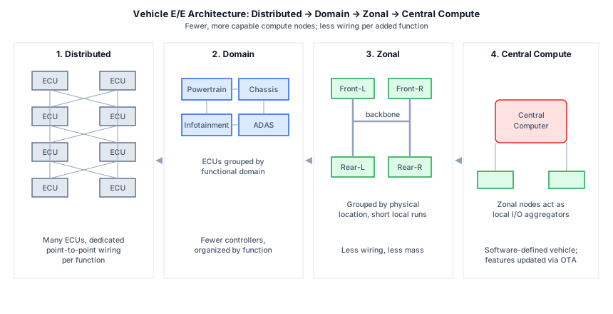
Vehicle electrical/electronic (E/E) architecture has evolved in a fairly consistent direction across the industry, driven by wiring cost, weight, and the demands of the software-defined vehicle:
- Distributed — the traditional approach: a dedicated electronic control unit (ECU) for each function, each wired individually to its sensors and actuators. Simple to reason about function-by-function, but the wiring harness grows heavy, expensive, and complex as functions multiply.
- Domain — ECUs are grouped by functional domain (powertrain, chassis, infotainment, ADAS), each domain controller handling several related functions. This reduces ECU count and simplifies software organization along functional lines.
- Zonal — controllers are grouped by physical location in the vehicle (front, rear, left, right) rather than by function, so nearby sensors and actuators connect to the nearest zonal controller over a short wiring run, and zonal controllers communicate with each other and a central computer over a high-speed backbone. This meaningfully cuts wiring length, weight, and harness complexity.
- Central compute — a small number of powerful central computers absorb most of the compute-heavy logic, with zonal controllers acting mainly as local I/O aggregators.
FACT — Zonal architecture combined with central compute is generally considered the technical foundation of the “software-defined vehicle” — it decouples software update cycles from hardware wiring, since new functionality often means a software change in the central computer rather than a new ECU and a new wiring branch. This is also what makes meaningful over-the-air (OTA) feature updates practical at scale. The trade-off is that software complexity, cybersecurity surface, and system validation effort all increase.
4. Trade-off Analysis Framework
INTERPRETATION — There is no universally “best” architecture; the right choice depends on the specific program’s constraints. A structured trade-off analysis typically weighs:
| Dimension | What to consider |
|---|---|
| Cost | Development, tooling, and per-unit hardware/wiring cost |
| Packaging | Interior space, floor height, crash structure fit |
| Serviceability | Field repair cost and complexity over vehicle lifetime |
| Manufacturing complexity | Assembly steps, supplier coordination, quality control |
| Thermal | Cooling paths for battery, power electronics, compute |
| Crash performance | Load paths around the battery and compute hardware |
| Scalability | How well the architecture stretches across a model family |
| Software complexity | Update cycle speed, validation effort, cybersecurity surface |
No single architecture dominates on every dimension simultaneously — a CTC battery improves mass efficiency but hurts serviceability; a zonal/central E/E architecture improves update agility but raises software validation burden. This is why architecture decisions are made at the program level against specific requirements, not as a universal template.
5. FAQ
How do manufacturers choose between domain and zonal E/E architectures?
FACT — The decision weighs vehicle class, the number of electronic functions, wiring cost sensitivity, and how much software update agility the program needs. Zonal architecture favors wiring and weight reduction; domain architecture favors keeping related functions organizationally and technically together, which can simplify validation for a given function group.
What does “central compute” actually replace?
FACT — It consolidates logic previously spread across many separate ECUs into a small number of powerful central computers, simplifying software update management and reducing the total ECU count — though the zonal controllers handling local I/O still remain.
Is CTC always better than CTM because it’s more efficient?
INTERPRETATION — Not universally — CTC’s mass and packaging efficiency comes at a real cost in serviceability and repair complexity after a collision. For vehicle classes where long service life and repairability matter more than maximum range or minimum mass (some commercial applications, for example), a less integrated approach can be the better engineering choice.
6. Summary
- Platform strategy spans ICE-derived, dedicated, skateboard, and modular approaches, each with a distinct cost/packaging/scalability profile.
- Battery integration has moved from cell-to-module toward CTP and CTC, trading serviceability for mass and space efficiency.
- E/E architecture has evolved from distributed through domain and zonal toward central compute, driven by wiring cost and the demands of the software-defined vehicle.
- Every architecture choice is a requirement-based trade-off across cost, packaging, serviceability, manufacturing, thermal, crash, scalability, and software complexity — there is no single universally correct answer.
7. Sources and Verification Note
No model-specific architecture claim is used in this lesson. The concepts are established, textbook-level engineering knowledge.
- SAE J1715 — Hybrid and electric vehicle terminology.
- U.S. DOE, Alternative Fuels Data Center.
Next Lesson
- EV-24 — Vehicle Configurations: single/dual/tri/quad motor layouts and torque vectoring.
Technical Diagrams
Quiz
How is the architecture decision handled in this lesson?
Architecture selection is done via requirement-based trade-off analysis; there is no single 'best'.
What does CTP (Cell-to-Pack) skip?
CTP skips the module level and places cells directly into the pack.
What is the drawback of CTC (Cell-to-Chassis)?
CTC is efficient, but because cells integrate into the chassis, service becomes harder.
What is the advantage of zonal over domain architecture?
Zonal architecture groups by location, reducing wiring.
What is central compute + zonal the basis of?
Central compute + zonal forms the basis of the software-defined vehicle.
What is the advantage of a modular platform?
A modular platform enables reuse/scalability across models.