
- Define ADAS (Advanced Driver Assistance Systems) and explain its core active safety architecture.
- Distinguish between passive safety and active safety in time domain and physical intervention.
- Analyze the Sense → Perceive → Plan → Act four-stage engineering pipeline at the sensor and actuator level.
- Compare Fail-Safe (graceful shutdown) and Fail-Operational (fault-tolerant continuity) system paradigms.
- Summarize ADAS's historical evolution — from adaptive cruise control to the DARPA Grand Challenge, Tesla Autopilot, and Waymo — and this academy's 30-lesson roadmap.
AD-01 — What Is ADAS? Fundamental Principles and Historical Evolution
ASSUMPTION — This lesson is the entry point of the AUTOVOLTIX ADAS & AUTOMATED DRIVING ACADEMY. The conceptual foundation built here — sensing, decision-making, actuator control, and functional safety boundaries — is the backbone the entire 30-lesson track builds on, from sensors (AD-04/05) to perception fusion (AD-06/07), planning (AD-09/10/11), and functional safety (AD-19/20).
In this lesson, you will learn:
- Define ADAS (Advanced Driver Assistance Systems) and explain its core active safety architecture.
- Distinguish between passive safety and active safety in time domain and physical intervention.
- Analyze the Sense → Perceive → Plan → Act four-stage engineering pipeline at the sensor and actuator level.
- Compare Fail-Safe (graceful shutdown) and Fail-Operational (fault-tolerant continuity) system paradigms.
- Summarize ADAS’s historical evolution and this academy’s roadmap.
- The Engineering Definition and Scope of ADAS
- The Four-Stage Pipeline: Sense → Perceive → Plan → Act
- Why Automotive Software Is Different: Functional Safety and Redundancy
- A Short but Accurate History: From Cruise Control to Waymo
- The Academy’s Roadmap
1. The Engineering Definition and Scope of ADAS
FACT — ADAS (Advanced Driver Assistance Systems) refers to the integrated set of sensors that perceive the vehicle’s surroundings (camera, radar, ultrasonic, LiDAR), the electronic control units (ECU / domain controllers) that process this data, and the actuators that can intervene in vehicle dynamics (EPS steering, e-Booster/ESP brakes, powertrain) — all working together to improve driver safety and comfort. The critical point: in ADAS, ultimate legal and operational responsibility for driving always rests with the human driver — this is the exact dividing line that separates ADAS from the Automated Driving System (ADS) definition detailed in AD-02.
Automotive safety has historically been divided into two fundamental phases:
- Passive Safety: Focuses on protecting occupants and pedestrians after a collision has already occurred. Crumple zones, airbags, and pyrotechnic seatbelt pretensioners belong to this class. Energy has already converted to kinetic form; the goal is to dissipate it in a controlled way.
- Active Safety (ADAS): Focuses on preventing the collision from happening at all, or minimizing kinetic energy at the moment of impact. ABS, ESC, AEB (Automatic Emergency Braking), and LKA (Lane Keeping Assist) belong here. The goal is to stop the energy from ever converting to kinetic collision energy, or to reduce it beforehand.
| Attribute | Passive Safety | Active Safety (ADAS) |
|---|---|---|
| Intervention Window | At impact and after (0 – 200 ms) | Before impact (t > 1.5 – 3.0 seconds) |
| Primary Goal | Reduce injury/fatality severity | Prevent the collision entirely / reduce speed |
| Core Hardware | Accelerometers, pyrotechnic charges, chassis | Camera, radar, LiDAR, smart brake/steering |
| Energy Management | Absorb kinetic energy | Eliminate kinetic energy via controlled braking |
| Example Technology | Airbag, pretensioning seatbelt, crumple zones | ABS, ESC, AEB, ACC, LKA, BSD |
| Failure Mode | Structural (deformation capacity exhausted) | Perceptual (sensor/algorithm makes a wrong call) |
INTERPRETATION — Modern Euro NCAP rating now bases the majority of a vehicle’s overall safety score on ADAS (the Safety Assist score); passive safety (structural crash testing) alone can no longer secure a 5-star rating. This is a clear signal that active safety has become a regulatory requirement, not a marketing feature.
2. The Four-Stage Pipeline: Sense → Perceive → Plan → Act
FACT — Regardless of brand or feature name (Automatic Emergency Braking, Lane Keeping, Adaptive Cruise Control, Highway Pilot), every ADAS/AD system runs the same four-stage engineering pipeline. This pipeline repeats continuously over automotive-grade CAN FD, FlexRay, or Automotive Ethernet buses, typically at 10–50 ms cycle times.
[ ENVIRONMENT ]
   │
   ▼
1. SENSE ──────────────────► Camera, Radar, Ultrasonic, LiDAR, IMU, GNSS
   │  Raw signal: pixel matrix, radar point cloud, ToF distance list
   ▼
2. PERCEIVE ───────────────► Object detection + classification + tracking + sensor fusion
   │  Output: "a passenger car, 35m ahead, closing at −60 km/h relative speed"
   ▼
3. PLAN ───────────────────► Behavior & trajectory planner (TTC calc, maneuver selection)
   │  Output: "−8 m/s² emergency deceleration" or "0.3 rad steering angle"
   ▼
4. ACT ────────────────────► ESP/e-Booster brake, EPS steering, inverter/throttle
   │
   ▼
[ VEHICLE MOTION ] ────────► Updates the environment state (Closed Loop)
Each stage is deep enough to warrant its own dedicated lessons later in the academy:
- Sense (AD-04, AD-05): The physical operating principle of each sensor (radar Doppler effect, LiDAR ToF, camera CMOS) and its physical limitations (resolution, range, weather sensitivity).
- Perceive (AD-06, AD-07, AD-08): Converting raw sensor data into a “world model” — object detection, classification, multi-frame tracking, sensor fusion (early/late/deep fusion), and localization.
- Plan (AD-09, AD-10, AD-11): Estimating the intent of other road users (prediction), behavior planning (change lane / wait / pass), and converting that decision into a geometric trajectory.
- Act: The low-level control loops that physically realize the planned trajectory (steering torque, brake pressure, torque command) — detailed in AD-11.
CRITICAL — The simplified, three-stage “Sense-Plan-Act” model common in popular explanations quietly folds the Perceive stage into Sense. This is engineering-misleading: a raw radar point cloud or camera pixel matrix is not, by itself, an “object” — a separate, computationally heavy perception layer decides that a given cluster of points is a “car,” a “pedestrian,” or simply “noise.” This academy deliberately separates these two stages because the entirety of AD-06/AD-07 is built on this distinction.
EXAMPLE — In an AEB (Automatic Emergency Braking) scenario, the four stages unfold as follows:
- Sense: The windshield-mounted mono camera and the 77 GHz radar behind the front grille detect a stationary vehicle ahead. The camera produces a raw pixel stream; the radar produces a raw point cloud (distance = 35 m, relative speed = −60 km/h).
- Perceive: A sensor fusion algorithm merges the camera and radar detections into a single tracked object: class = “passenger car,” with a position/velocity covariance and a single confidence score.
- Plan: The ADAS ECU computes Time-to-Collision (TTC = 35 / 16.6 ≈ 2.1 seconds). It verifies the driver has not applied the brakes and issues an emergency deceleration command of −8 m/s².
- Act: The decision is relayed over CAN FD to the ESP / electronic brake booster (e-Booster). Hydraulic pressure ramps to 100 bar within 40 ms, bringing the vehicle to a stop.
3. Why Automotive Software Is Different: Functional Safety and Redundancy
When a mobile app crashes, the user restarts it. When ADAS software crashes at 120 km/h, the outcome can be irreversible. This asymmetry is what fundamentally separates automotive software from consumer software, and it is the reason ISO 26262 (Road Vehicles — Functional Safety) exists as a standard; it will be covered in depth in AD-19.
Two core architectural paradigms govern functional safety design in ADAS systems:
-
Fail-Safe (Graceful Shutdown):
- When the system detects a hardware fault, sensor occlusion, or software anomaly, it disables the function in a controlled manner and immediately hands control back to the human driver.
- Example: A Lane Keeping Assist (LKA) system disengaging with an audible warning when the camera lens is obscured by snow. All L0, L1, and L2 ADAS systems are fundamentally fail-safe — because even in the “off” state, the driver is already the primary operator, so the vehicle is never left uncontrolled.
-
Fail-Operational (Fault-Tolerant Continuity):
- Even if the primary component fails, the system continues its function safely thanks to redundant secondary hardware.
- Example: In L3/L4 automated driving systems, if the primary steering ECU fails, a second, independently wound EPS motor (dual-winding EPS) and a second, independently powered brake actuator keep the vehicle safely within its lane and bring it to a Minimal Risk Condition (MRC).
| Criterion | Fail-Safe | Fail-Operational |
|---|---|---|
| Post-Fault State | Function disengages, human takes over | Function continues (even if degraded) |
| Required Hardware Redundancy | Single channel sufficient | Dual/triple channel (dual EPS, dual brake, second power line) |
| Typical SAE Level | L0 – L2 | L3 – L4 (L5 mandates it by definition) |
| Assumption | Human is ready to take over at any moment | Human may not take over, or may not be present at all |
| Cost Impact | Low (single sensor/actuator set) | High (redundant power, compute, and communication paths) |
CRITICAL — For L1 and L2 systems, where continuous human supervision is mandatory, fail-safe is considered sufficient. But for L3 conditional automation and driverless L4 systems, where instantaneous human intervention is not expected, hardware- and electrically-fail-operational architecture is both a legal and technical requirement. This is the direct reason X-by-Wire architectures (steer-by-wire, brake-by-wire) require redundant power sources, redundant processors, and redundant communication buses — in a system with no mechanical fallback path to a steering column, an electronic fault equals total loss of control.
4. A Short but Accurate History: From Cruise Control to Waymo
| Year | Milestone | Engineering Significance |
|---|---|---|
| 1958 | Chrysler introduces a mechanical “cruise control,” patented by Ralph Teetor, on the Imperial. | The first longitudinal automation — speed is held constant, but environmental perception is zero; it will collide with a vehicle ahead. |
| 1995 | Mitsubishi (Japan market, Debonair) launches one of the first laser-based adaptive cruise control systems. | For the first time, a system adjusts speed relative to the vehicle ahead — a primitive Sense→Act loop. |
| 1999 | Mercedes-Benz S-Class (W220) introduces radar-based Distronic ACC. | Mass-production entry of radar-based ACC; unlike laser, radar performs far better in rain and fog. |
| Mid-2000s | Manufacturers like Honda and Toyota introduce camera-based Lane Keeping Assist (LKA). | First lateral-axis automation; longitudinal (ACC) and lateral (LKA) remain separate, independent systems. |
| 2004–2007 | DARPA Grand Challenge: in 2004, no vehicle finishes the desert course; in 2005, Stanford’s “Stanley” (Sebastian Thrun’s team) wins; in the 2007 Urban Challenge, CMU’s “Boss” completes a simulated urban-traffic course. | Ignites an explosion of academic/industrial research into the modern perception stack (LiDAR-based mapping, probabilistic sensor fusion, real-time path planning); many engineers from these competitions later founded what became Google’s self-driving project — the precursor to Waymo. |
| 2014 | Tesla launches a system it names “Autopilot” on the Model S, built on Mobileye EyeQ3 hardware. | Brings combined longitudinal+lateral control (SAE Level 2) to the mass consumer market and popularizes the term “autonomous driving” in mainstream culture — fueling the naming controversy examined in AD-03. |
| 2020 (December) | Waymo opens a fully driverless robotaxi service — with no safety driver — to the public in Phoenix, Arizona. | Concrete proof of a real commercial SAE Level 4 service operating within a bounded ODD — examined in depth in AD-03 and AD-15. |
| 2021–2022 | Mercedes-Benz Drive Pilot receives type approval in Germany under UNECE R157 (ALKS), followed by select state approvals in Nevada and California. | A real, narrowly-certified SAE Level 3 example operating within a specific, narrow ODD (highway, ≤60 km/h, traffic-jam conditions) — used as a case study in AD-03. |
ASSUMPTION — Some “first-of-its-kind” claims in the table above may vary slightly between industry sources; while the technology leap between Mitsubishi’s 1995 laser system and Mercedes’ 1999 radar system (laser vs. radar) is well established, exactly which model deserves the “world’s first” title can differ from source to source. What matters for this lesson is the chronology and the technology jump, not an absolute priority claim.
5. The Academy’s Roadmap
This lesson is only the first step of the 30-lesson AUTOVOLTIX ADAS & Automated Driving Academy. The lessons ahead are organized around eight core tracks:
| Track | Lesson Range | Focus |
|---|---|---|
| Fundamentals | AD-01 – AD-03 | Definitions, DDT, SAE J3016 taxonomy (you are here) |
| Sensors | AD-04 – AD-05 | Physics and limitations of camera, radar, LiDAR, ultrasonic, IMU, GNSS |
| Perception & Fusion | AD-06 – AD-08 | Object detection, sensor fusion architectures, localization (SLAM, HD maps) |
| Planning & Control | AD-09 – AD-11 | Intent estimation, behavior/trajectory planning, lateral-longitudinal control |
| Features & Architecture | AD-12 – AD-15 | Concrete features like AEB/ACC/LKA, highway pilot, automated parking, robotaxi architecture |
| Safety & Cybersecurity | AD-16 – AD-21 | ODD, fallback/MRM, DMS, ISO 26262, SOTIF, ISO/SAE 21434 |
| Validation & Testing | AD-22 – AD-25 | MIL/SIL/HIL/VIL, scenario-based testing, edge cases, adverse weather |
| Regulation & Future | AD-26 – AD-30 | Global regulations, manufacturer review, safety case (UL 4600), future E/E architectures |
FAQ
Q: Are ADAS and Automated Driving the same thing?
FACT — No. ADAS assists the driver while responsibility remains entirely with the human (L0–L2). Automated Driving Systems (ADS) refer to levels (L3–L5) where the system assumes the full driving task and legal responsibility within a defined Operational Design Domain (ODD). This distinction will be formalized in AD-02.
Q: Why does ADAS disable itself in rain or snow?
FACT — An unwipeable camera lens, wet snow buildup on the radar radome, or lane markings obscured by standing water all reduce sensor confidence scores. The fail-safe architecture disengages the system into a safe mode to avoid false-positive interventions. This is covered in depth in AD-05 and AD-25.
Q: Why is the DARPA Grand Challenge considered so important?
FACT — In the first 2004 race, no vehicle completed the 240 km desert course (the best team only managed about 12 km). This “failure” demonstrated to the academic and industrial community just how hard real-world automated driving actually is, and triggered intense research investment in perception, planning, and mapping over the following three years — a significant portion of today’s leading autonomous driving companies’ core engineering talent traces directly back to these competitions.
Safety Notice (Functional Safety & Responsibility)
[!IMPORTANT] L1 and L2 ADAS features (ACC, Lane Centering, Highway Assist) absolutely do not make a vehicle “drive itself.” The driver must keep their hands on the wheel, continuously monitor the road, and remain ready for mechanical intervention at all times. This principle will be made concrete in AD-03 through the “Tesla naming controversy” case study.
Summary
- ADAS is a class of active safety technologies aimed at preventing crashes; unlike passive safety, it engages before impact.
- Every ADAS/AD system, regardless of brand name, runs the Sense → Perceive → Plan → Act pipeline; the Perceive stage converts raw sensor data into a world model.
- Automotive software falls under the ISO 26262 functional safety framework due to its safety-critical nature; L0-L2 systems require fail-safe architecture, L3+ systems require fail-operational architecture.
- ADAS’s history is a continuous evolution — from 1958’s mechanical cruise control to 1999’s radar-based ACC, from the 2004-2007 DARPA Grand Challenge to 2014’s Tesla Autopilot, to Waymo’s driverless robotaxi service in 2020.
- This academy covers that evolution in engineering depth across 30 lessons organized into eight tracks: Fundamentals, Sensors, Perception & Fusion, Planning & Control, Features & Architecture, Safety & Cybersecurity, Validation & Testing, and Regulation & Future.
Sources & Verification Note
Sources: SAE J3016 Taxonomy, ISO 26262:2018 Road Vehicles — Functional Safety, Winner et al. — Automotive Handbook on ADAS, Thrun et al. — “Stanley: The Robot that Won the DARPA Grand Challenge” (Journal of Field Robotics), NHTSA — Automated Driving Systems 2.0: A Vision for Safety. The historical dates and technical thresholds in this lesson (e.g., ACC range/speed values, DARPA Grand Challenge outcomes) are verified against public manufacturer announcements and academic literature; claims flagged as ASSUMPTION regarding “first-of-its-kind” titles may vary slightly between sources.
Next Lesson
- AD-02 — What Is Automated Driving? The Automation Spectrum: Decomposing the Dynamic Driving Task (DDT) into lateral control, longitudinal control, and OEDR sub-tasks; why the engineering community is moving away from the word “autonomous”; and the automation complacency risk at the L2/L3 boundary.
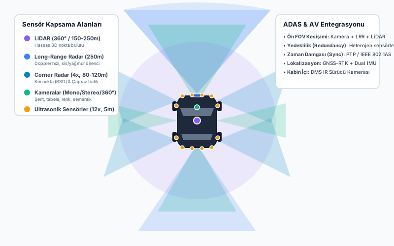
Technical Diagrams
Quiz
Which safety category do ADAS features fundamentally belong to?
ADAS belongs to active safety, aiming to prevent collisions before they occur.
What is the correct sequence of the core autonomous control loop?
The loop is Sense (Perception) → Plan (Decision) → Act (Execution).
What is the key engineering difference between Fail-Safe and Fail-Operational?
Fail-Safe safely deactivates, whereas Fail-Operational maintains control through redundancy.
How is Time-to-Collision (TTC) computed in an AEB decision gate?
TTC = relative_distance / relative_velocity.
Why is Fail-Operational architecture strictly required for Level 4 systems but not Level 2?
Level 2 relies on human supervisory fallback; Level 4 ADS must autonomously handle its own failures.
Glossary
| English Term | Definition |
|---|---|
| Advanced Driver Assistance Systems (ADAS) | Electronic and algorithmic active safety systems designed to enhance driver situational awareness, issue warnings, or intervene via steering/braking to mitigate collisions. |
| Autonomous Emergency Braking (AEB) | An active safety system that monitors the forward path using radar/camera fusion and automatically commands emergency deceleration when an imminent collision is detected and the driver fails to react. |